background image

─ 9 ─

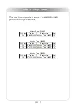
SHCS = Socket Head Cap Screw

FHCS = Flat Head Cap Screw

HHB = Hex Head Bolt

BHCS = Button Head Cap Screw

Measurement Guide

Summary of Contents for IF8110

Page 1: ......

Page 2: ...this equipment CAUTION Important Safety Instructions 3 Instructions 4 Parts List 5 Exploded View 8 Measurement Guide 9 Assembly Instructions 10 Assembly 11 Exercise Instructions 21 Maintenance Schedu...

Page 3: ...it has been dropped or damaged Never drop or insert anything into any opening in the equipment Always check the unit and its cables before each use Make sure that all fasteners and cables are secure...

Page 4: ...nal injury The equipment is designed to provide the smoothest most effective exercise motion possible After assembly you should check all functions to ensure correct operation If you experience proble...

Page 5: ...hroud 1 21 SG500110400 4 5 Pulley 5 22 CWRVL0052100P166C Handball 1 23 IF81102300 Cable 1 24 IF81162700 Plastic Plate 128 5 121 9 1 5 2 25 IF81102500 Seat Pad 1 26 IF18602500 Back Pad 1 27 FS543400 Wh...

Page 6: ...DS20 Hex Head Bolt M12 65 1 73 GB5781M12 30DS20NL Hex Head Bolt M12 30 2 74 GB5780M10 130DS20 Hex Head Bolt M10 130 2 75 GB5780M10 110DS20 Hex Head Bolt M10 110 4 76 GB5780M10 105DS20 Hex Head Bolt M1...

Page 7: ...eight Plate 10LBS 10 101 IF8WS1500 Weight Plate 15LBS 6 Item No Part No Description Qty 101 IF8WS1500 Weight Plate 15LBS 16 Weight Plate 170LBS Weight Plate 200LBS Weight Plate 250LBS 7 Parts List Wei...

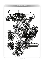
Page 8: ...8 Exploded View...

Page 9: ...9 SHCS Socket Head Cap Screw FHCS Flat Head Cap Screw HHB Hex Head Bolt BHCS Button Head Cap Screw Measurement Guide...

Page 10: ...e heavy or awkward to handle alone It is important that you assemble your product in a clean clear uncluttered area This will enable you to move around the product while you are fitting components and...

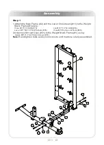
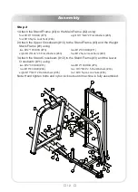
Page 11: ...Frame 1 using three M10 105 HHB 76 one M10 110 30 HHB 93 seven 11 23 2 Flat Washers 65 three M10 Nylon Lock Nuts 68 2 Attach six Shroud Clips 31 to the Weight Stack Frame 1 using twelve M5 15 Flat Ph...

Page 12: ...ack Frame 1 using two M12 105 HHB 70 two M12 80 HHB 71 eight 13 24 2 5 Flat Washers 63 four M12 Nylon Lock Nuts 67 3 Attach the Stand Crossbeam 12 to the Stand Frame 3 and the Lower Crossbeam 11 using...

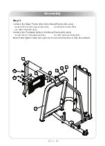
Page 13: ...ing two M10 25 Flat Head Cap Screws 95 two 38 6 End Caps 45 one 25 178 Shaft I 16 2 Attach the Footplate 14 to the Sway Frame 4 using four 13 4 2 5 Flat Washers 63 four M12 Nylon lock Nuts 67 Note Han...

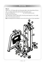
Page 14: ...e Main Frame 2 and the Stand Frame 3 using five M10 50 HHB 81 ten 11 23 2 Flat Washers 65 five M10 Nylon Lock Nuts 68 The Cable 23 and the Pulleys 21 must be placed together or the Cable 23 can not be...

Page 15: ...two 76 2 26 9 38 1 Weight Rubber Bumpers 36 to the Weight Stack Frame 1 using two 40 25 Mount Sleeves 50 four M8 8 Socket Set Screws 84 2 Attach the Selector Pin W Coil 35 to the Top Plate 33 3 Attach...

Page 16: ...op Plate 33 two 76 2 26 9 38 1 Weight Rubber Bumpers 36 to the Weight Stack Frame 1 using two 40 25 Mount Sleeves 50 four M8 8 Socket Set Screws 84 2 Attach the Selector Pin W Coil 35 to the Top Plate...

Page 17: ...two 76 2 26 9 38 1 Weight Rubber Bumpers 36 to the Weight Stack Frame 1 using two 40 25 Mount Sleeves 50 four M8 8 Socket Set Screws 84 2 Attach the Selector Pin W Coil 35 to the Top Plate 33 3 Attach...

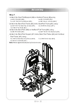
Page 18: ...82 three 11 23 2 Flat Washers 65 3 Attach the Left Handle 9 and the Right Handle 10 to the Seat Pad Frame 5 using two M10 100 HHB 77 four 11 23 2 Flat Washers 65 two M10 Nylon Lock Nuts 68 4 Insert th...

Page 19: ...Pad Frame 5 using two M10 25 Flat Head Cap Screws 95 two 38 6 End Caps 45 one 25 4 120 Shaft 41 3 Attach the Back Pad 26 to the Back Pad Frame 6 using two M10 50 HHB 81 two 11 23 2 Flat Washers 65 4...

Page 20: ...gh Rear Shroud 18 and the High Front Shroud 19 to the Weight Stack Frame 1 2 Attach the Top Shroud 20 to the Weight Stack Frame 1 using two M6 15 BHCS 85 two 6 6 15 2 Flat Washers 66 Note Wrench Tight...

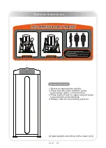
Page 21: ...et shoulder width on plate extend legs with a control motion 3 Place balls of feet on upper edge of plate Legs straight extend ankles 4 Slowly return to the starting position Exercise Instructions Adj...

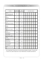
Page 22: ...nsion DAILY WEEKLY Inspect Accessory Bars and Handles WEEKLY 3 MONTHS Inspect All Decals WEEKLY 3 MONTHS Inspect All Nuts and Bolts Tighten if needed WEEKLY 3 MONTHS Inspect Anti Skid Surface WEEKLY 3...

Page 23: ...oting and need to be replaced if they appear worn or become slippery Belts and Cables We uses only high quality belt and mil spec cables Visually inspect the belts and cables for fraying cracking peel...

Page 24: ...o get started immediately First determine a set of realistic goals and objectives for yourself By deciding on an exercise plan that is right for you prior to starting you will contribute significantly...

Page 25: ......

Reviews: