background image

PowerLock

FOR GRAIN TRAILERS

12

Installation Instructions

Step 3a

Marking Bow Location

1)

 Mark top rail according to what caps are on the trailer.

First bow 
after cap

Equally spaced 

not to exceed 48"

18"

18"

Front

T

ailgate

Fabric Front Cap

Fabric Rear Cap

First bow 

before cap

18"

Equally spaced 

not to exceed 48"

18"

Front

T

ailgate

Aluminum Front Cap

Aluminum Rear Cap 

Mounted to Tailgate

First bow 

before cap

First bow 
after cap

Equally spaced 

not to exceed 48"

18"

18"

20"

Front

T

ailgate

Aluminum Front Cap

Aluminum Rear Cap 

with Tail

First bow 

before cap

First bow 
after cap

Equally spaced not to exceed 48"

30"

Fabric Front Flap

Fabric Rear Tail

R, D or O

8" if square

First bow

Last bow

Equally spaced 

not to exceed 48"

18"

30"

Front

T

ailgate

Aluminum Front Cap

Fabric Rear Tail

First bow 
after cap

Last bow

18"

Front

Fabric Front Cap

Fabric Rear Tail

Equally spaced 

not to exceed 48"

30"

T

ailgate

First bow 
after cap

Last bow












Summary of Contents for PowerLock

Page 1: ...com Indianapolis IN Omaha NE Streetsboro OH Attention Dealers Please give this owners manual to the customer when the product is delivered Serving the Truck Trailer Industry Since 1944 FOR GRAIN TRAILERS PowerLock Installation Instructions ...

Page 2: ...13 Installing Adjustable Steel Bows 3c 13 Installing Heavy Duty Bows 3d 14 Installing Flex Bows 3e 15 Assembly Anchor Pipe and Roll Pipe 4a 16 Position Tarp on Trailer 4b 16 Installing Roll Stops and Secure Anchor Pipe 5 17 Install Latch Plate 6 18 Install PowerLock Pivot Box Front and Rear 7 19 Install PowerLock Spring Assembly Front and Rear 8 20 Install PowerLock Swing Arm Assembly Front and Re...

Page 3: ...re repairs Replace damaged or broken parts Keep path of arms clear YYY RQYGTNQEMOCKPVGPCPEG EQO 12 4 6 10 05647 6 105 Refer to Operations sheet or website Only drive with tarp in fully covered or uncovered position Routinely inspect tarp and arms and replace if damaged YYY RQYGTNQEMQRGTCVKQP EQO 1 016 UVCPF KP VJG RCVJ QH VJG HTQPV TGCT UYKPI CTOU QT KPLWT EQWNF QEEWT 5RTKPIU CPF CTOU CTG WPFGT GZ...

Page 4: ... Hammer Saw Hack Saw 1 1 8 hole saw Drill Bits 9 32 11 32 Sockets 5 16 7 16 9 16 3 4 Open End or Box Wrenches 5 16 7 16 9 16 3 4 Torx T40 Hex Key 5 16 Phillips 3 Electric or Air Drill Welder Tools Required for Installation This manual explains how to install and maintain a PowerLock Roll Tarp system ...

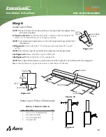
Page 5: ...so mark 10 from there for heavy duty bows The dimension of the Radius Diagonal or Offset Double Bow Bracket Heavy Duty Bows Figure 2 Figure 1 R Radius Corner Flat on side of trailer Front D S D Diagonal Corner Flat on side of trailer D S Front O Offset Corner Flat on side of trailer D S Front R D or O 10 Flat on side of trailer D S Front R D or O 10 Flat on side of trailer D S Front ...

Page 6: ... Figure 5 Attach with 3 8 x 2 1 2 carriage bolts Index Description Qty 1 Fabric Front Cap 1 2 Double Bow or Heavy Duty Bracket 2 3 Bows 2 Index Description Qty 4 3 8 x 1 Type F HWH 8 5 5 16 x 1 1 2 Type F Torx 15 6 Aluminum Flat Bar 1 8 x 1 12 ft 10 R D or O 10 R D or O Figure 3 Double Bow Bracket Heavy Duty Bows Figure 4 Hardware to Mount to Sideboards Index Description Qty 7 5 16 X 2 1 2 CARRIAG...

Page 7: ...tom of fabric cap 5 Figure 6 Feed bow through top of fabric cap 6 Figure 7 Pull cap tight over top rail 7 Figure 8 Drill holes evenly spaced through aluminum flat bar and attach with 5 16 x 1 1 2 Type F Torx Figure 6 Bow Through Pocket Fabric Front Cap Center Bolts Figure 7 Pull cap to tighten Gap Roll Tarp Fabric Cap No Gap Roll Tarp Fabric Cap Double Bow ...

Page 8: ...ler center and push lip up against the trailer 2 Figure 10 Trace the corner shape of nose onto front cap and cut out shape Index Description Qty 1 Front Cap Aluminum 1 2 Aluminum Strip 1 8 x 3 2 3 3 8 x 1 Type F HWH 4 3 Figure 11 Attach with 3 8 x 1 Type F HWH Bolts through trough into top rail 4 Figure 11 Shape the aluminum strip around the corner of the trailer mark and cut to length for both si...

Page 9: ...nt to Sideboards Index Description Qty 5 5 16 X 2 1 2 CARRIAGE BOLT 8 6 5 16 FLAT WASHER 8 7 5 16 LOCK WASHER 8 8 5 16 HEX NUT 8 Figure 15 Install Double Bow Bracket to Sideboards 1 Figure 13 Measure and mark 30 from the outside of the tailgate and 10 towards the rear from the previous mark 2 Figure 14 Clamp first pocket of double bow bracket centered on mark on top rail 3 Figure 14 Position brack...

Page 10: ...ter Bolts Bow Through Pocket Tail Fabric Rear Cap Figure 16 5 Figure 16 Feed bow through top of fabric cap and install on trailer 6 Figure 17 Pull cap tight when securing with Latch Plate or Roll Stop No Gap Roll Tarp Fabric Cap Figure 17 Gap Roll Tarp Fabric Cap ...

Page 11: ...ap centered on inside of tailgate with the bottom of the trough even with the side walls 2 Drill pilot holes and secure with 3 8 x 1 Type F HWH bolts 1 Figure 1 Position aluminum rear cap on top rail centered on width locate the front edge of cap 20 from outside of tailgate 2 Drill pilot holes and secure with 3 8 x 1 Type F HWH bolts 3 Figure 20 Insert welt on tail into Keder on back of cap and ce...

Page 12: ...ear Cap Mounted to Tailgate First bow before cap First bow after cap Equally spaced not to exceed 48 18 18 20 Front Tailgate Aluminum Front Cap Aluminum Rear Cap with Tail First bow before cap First bow after cap Equally spaced not to exceed 48 30 Fabric Front Flap Fabric Rear Tail R D or O 8 if square First bow Last bow Equally spaced not to exceed 48 18 30 Front Tailgate Aluminum Front Cap Fabri...

Page 13: ...with the top rail 2a Figure 24 Drill a pilot hole and attach with 3 8 x 1 type F HWH bolts 2b Figure 25 Drill a pilot hole and attach with 3 8 x 1 type F HWH bolts 3 Figure 26 Loosen set screw on bow Insert bow into pockets into one pocket and adjust width and insert in other pocket and tighten set screw Mark on top rail 3 8 x 1 Type F HWH Figure 21 Figure 22 Set Screw Figure 26 Bracket can be pos...

Page 14: ... Figure 28 Attach swivel bracket assembly to base with headless pin and cotter pins 4 On opposite side attach heavy duty bow assembly with headless pin and cotter pin Figure 27 3 8 x 1 Type F HWH Mark on top rail Cotter Pins Headless Pin Swivel Bracket Assembly Figure 28 Figure 30 Mark and cut bow Figure 29 5 Figure 29 Mark heavy duty bow assembly disassemble and cut to length 6 Figure 30 Reassemb...

Page 15: ...talling Flex Bows BOLT 1A Figures 31 Align pocket with marked bow location and flush with top of rail Drill a pilot hole and attach with 3 8 x 1 type F HWH bolts WELD 1B Figure 31 32 Align pocket with marked bow location and flush with top of rail Weld all around pocket Mark on top rail 3 8 x 1 Type F HWH Figure 31 Bolt Figure 32 Weld Mark on top rail Figure 33 For sideboard installation weld a pl...

Page 16: ...he tarp front to back accordingly Figure 39 Figure 40 2 See Figure 38 Cut the anchor pipe flush with the ends of the pocket on the tarp 3 Place rubber cups on ends of anchor pipe 4 See Figure 38 Slide the anchor pipe into the tarp pocket and secure with 14 x 1 PPH self drilling screw at each end 5 See Figure 38 Slide the roll pipe into the other pocket and leaving 1 4 sticking out at the REAR of t...

Page 17: ...acket 4 8 from end of anchor pipe or as close as possible and 1 down from top rail 5 Evenly space roll stop brackets along top rail with maximum of 96 apart 6 Place anchor pipe into roll stop and assemble roll stop Roll Stop Bracket 4 8 as close as possible each end 1 Figure 41 Install Anchor Pipe Roll Stops to Sideboards Install Anchor Pipe to Top Rail Roll Stops to Sideboards Hardware to Mount t...

Page 18: ...e F HWH bolts 3b Figure 47 Attach with 3 8 x 2 1 2 carriage bolts 4 Cut the last section so it goes back at least 3 past the end of the tarp Step 6 Install Latch Plate 24 2 4 Top Rail Latch Plate 24 Typical 2 4 Figure 46 Figure 44 Front Edge of Tarp Latch Plate 3 Figure 45 Top Rail 1 to 5 Maximum Latch Plate 3 8 x 1 Hardware to Mount to Sideboards Index Description Qty 1 5 16 X 2 1 2 CARRIAGE BOLT...

Page 19: ...t 8 7 3 8 16 Nylon Hex Nut 8 8 3 8 Flat Washer 8 1 See Figure 48 Attach the mounting plate to the pivot box with the provided fasteners 2 See Figure 49 At the FRONT and REAR of the trailer find location for pivot box mount 3 See Figure 50 Drill clearance holes and secure with 3 8 16 x 2 3 4 hex bolt washers and nylon nut Figure 48 Pivot Box Mounting Plate 1 2 13 X 1 3 4 FHCS 1 2 FLAT WASHER 1 2 13...

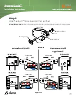
Page 20: ...ate and secure with collar and screw Step 8 Install PowerLock Spring Assembly Front and Rear Figure 52 D S Front View Figure 51 Spring Assembly Mounting Plate Collar and Screw Rear View Washer Washer REAR FRONT D S Rear View Front View D S Rear View D S FRONT REAR Standard Roll Reverse Roll Optional Ä Ä Ä Ä Ä Ä Ä Ä Ä Ä Ä Ä ...

Page 21: ...thru hole in tube and tighten second bolt against tube Figure 54 Front Swing Arm Assembly Spring Assembly Remove collar before inserting into Spring Assembly Figure 55 Step 9 Install PowerLock Swing Arm Assembly Front and Rear Figure 53 Figure 56 Figure 57 Rear Swing Arm Assembly Spring Assembly Remove collar before inserting into Spring Assembly 3 See Figures 56 57 Remove bottom collar insert swi...

Page 22: ...drive adapter into the front end of the roll pipe and weld in place Figure 59 Drive Adapter Weld Roll Pipe Figure 61 7 See Figure 61 Slide the shaft collar 5 and the rear swing arm onto the adapter shaft at the rear of the trailer Re check the pivot box face for plumb Place the shaft collar 5 1 4 from the swing arm bushing and tighten 1 See Figures 58 Attach the snap pin drive adapter to the drive...

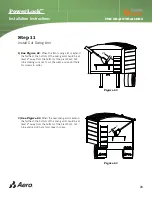
Page 23: ...away from the bottom of the pivot boot Cut tube making sure not to cut the wires and re drill hole for screws in collar Figure 62 2 Step 11 Install Cut Swing Arm 2 Figure 63 2 See Figure 63 When the rear swing arm is extend the farthest the bottom of the swing arm should be at least 2 away from the bottom of the pivot boot Cut tube and re drill hole for screws in collar ...

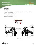
Page 24: ...dry area 3 Remove backing and adhere label to trailer 4 Repeat for the rear of the trailer Step 12 Place Labels Standard Roll Reverse Roll Optional CDGN 2CTV Ä 5RTKPIU CPF CTOU CTG WPFGT GZVTGOG VGPUKQP 1 016 UVCPF KP VJG RCVJ QH VJG UYKPI CTOU 0 8 4 UVCPF PGCT FCOCIGF CTOU VCTR TQMGP QT FCOCIGF EQORQPGPVU EQWNF ECWUG FGCVJ QT UGTKQWU KPLWT Place label at eye level on side opposite of the anchor p...

Page 25: ...PowerLock FOR GRAIN TRAILERS 25 Installation Instructions Page Intentionally left blank ...

Page 26: ...e Operation Maintenance Sheet and keep near switch 2TQPI 2NWI CWIG 9KTG 4QEMGT 5YKVEJ 4GXGTUKPI QPVCEVQT CWIG 9KTG 2 Mount reversing contactor outside near back of cab with 1 4 20 x 2 hex bolts 4 Connect breaker to battery and secure with zip ties 3 Run wire from switch to reversing contactor Run wire from battery to reversing contactor Secure all wire with clamps 5 Run wires from reversing contac...

Page 27: ...inal 1 Terminal 2 Terminal 1 Blue to T1 Green to T2 Red to BAT Black to GND 2 Connect remote receiver to reversing DC Contactor Secure all wire with clamps Locate Operation Maintenance Sheet and keep in a convenient location 1 Mount the remote receiver to the back of the cab with the provided screws The optional remote kit replaces the use of the rocker switch Follow steps 12a and 12b and replace ...

Page 28: ... Mount receptacle in convenient location on trailer 1 Connect breaker to battery and secure with zip ties POS NEG Locate Operation Maintenance Sheet and keep in a convenient location Semi trailer Truck Wiring Semi trailer Wiring 2 Run wire from battery to receptacle Secure all wire with clamps ...

Page 29: ...GND FWD REV Terminal 2 Terminal 1 Red to BAT Black to GND 6 Connect remote box to reversing DC Contactor Secure all wire with clamps 7 Connect receptacle to reversing DC contactor Secure all wire with clamps 4 Mount reversing contactor under the nose of the trail with 1 4 20 x 2 hex bolts 5 Mount the remote receiver to the back of the cab with the provided screws GND BAT ...

Page 30: ...se when fully covered Push to uncover unit and release when fully uncovered Switch Remote Operation Push to uncover unit and release when fully covered Push to cover unit and release when fully uncovered Receiver Key FOB Tarp IC 6265A 1500R Made in the USA P1555 AER 05 SN 800 535 9545 Manual Switch Uncover Cover ...

Page 31: ...rating oil DO NOT use an excessive amount of lubricant Springs Examine springs for breakage or distortion Apply a light coat of penetrating oil to tension springs as needed Fasteners Make sure that all mounting bolts and screws are in place and tight and that no parts are worn or damaged Chain Check the chain tension that links move smoothly and make sure the master link is on Lubricate the chain ...

Page 32: ...35 9545 www aeroindustries com INDIANAPOLIS IN Indianapolis IN 46241 800 535 9545 FAX 317 244 1311 OMAHA NE Omaha NE 68137 800 535 9545 FAX 402 895 6129 STREETSBORO OH Streetsboro OH 44241 800 535 8552 FAX 330 626 3277 2014 Aero Industries Inc ...

Reviews: