OPERATION MANUAL
SILA 450 c
AERO EAST EUROPE
Date 01.09.2015.
Revision 00
Page | 64
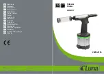
Picture 8.4:
Parachute connections to the aluminum plate
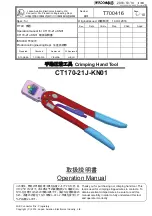
Parachute hole is located on the rear top part of the fuselage. Dimensions of the parachute
hole are given in the picture 8.5a.
Picture 8.5b shows parachute hole location on the SILA 450 C aircraft.
Picture 8.5a: Parachute hole
Plates for the
parachute connection