


20.05 – 4138421_03
13
The units may be available with or without integrated hydronic kit, in any
case:
ATTENTION The choice and installation of components external to the
unit is up to the installer, who must operate according to the rules of
good technical design and in compliance with the regulations in force in
the country of destination.
ATTENTION The hydraulic connection pipes to the unit must be suitably
dimensioned for the effective water flow rate requested by the system
when running. The water flow rate to the heat exchanger must always be
constant
ATTENTION Wash the system thoroughly before connecting the unit. This
cleaning will eliminate any residues such as welding drips, scale, rust,
or other impurities from the piping. These substances can also deposit
inside and cause unit malfunctions. The connection piping must be
adequately supported so that its weight does not rest on the appliance
CONNECTIONS
Before starting the system, check that the hydraulic circuits are connected
to the current exchangers (or, that the evaporator in the air/water units
or evaporator and condenser in the water water units or the intake and
flow fittings have not been reversed). The water circulation pump must
preferably be installed upstream so that the evaporator/condenser is
subject to a positive pressure. The water inlet and outlet connections are
indicated in the dimension tables in this manual, or available on www.
aermec.com
It is important to follow the recommendations (not complete) below:
• The water pipes must not transmit radial or axial forces or vibrations
to the exchangers (use flexible hoses to reduce the transmitted
vibrations)
• It is necessary to install manual or automatic vent valves in the highest
points of the circuit; and also provide discharge fittings in the lowest
points to allow emptying the entire circuit
• To maintain the pressure in the circuits, you must install an expansion
tank and a safety valve
• Respect the water inlet and outlet connections shown on the unit
• Install manometer
on the water inlet and outlet fittings.
• Install stop valve near the water inlet and outlet fittings.
• After performing a leak test, insulate the pipes to reduce heat loss and
prevent the formation of condensation
• If the external water pipes are in an area where it is likely that the
environment temperature drops below 0°C, insulate the pipes and
provide an electric heater. As an option, you can also protect the pipes
inside the unit.
• Check the continuity of the earthing.
ATTENTION You must install the water filter supplied, in the hydraulic
circuit upstream of the heat exchanger. FAILURE TO DO THIS
INVALIDATES THE WARRANTY.
ATTENTION The charge or discharge of the heat exchange fluids must
be made during installation by qualified technicians using the fittings
provided on the hydraulic circuit. Never use the unit heat exchangers to
top-up the heat exchanger fluid.
DISCHARGING SYSTEM
In the event the system is stopped during winter, the water in the heat
exchanger can freeze damaging the heat exchanger irreversibly. To prevent
danger of freezing, three solutions are possible:
1. Full water discharge from the unit.
2. Using the resistances. In this case the resistances must always be
supplied with electrical power for the entire period of possible freezing
(machine in stand-by).
3. Operation with glycol/water fluid, with a percentage of glycol based
on the minimum outdoor temperature expected.
ANTI-FREEZE PROTECTION
ATTENTION: the addition of glycol is the only effective protection
against freezing; the glycol/water solution must be sufficiently
concentrated to ensure proper protection and prevent ice forming
at minimum temperature provided for a given installation. Take the
necessary precautions if using non-passivated anti-freeze solutions
(monoethylene glycol or monopropylene glycol). Corrosion phenomena
may occur with these anti-freeze solutions in contact with oxygen.
However, always refer to the glycol supplier documentation to check its
recommended concentration.
HYDRAULIC CONNECTIONS
Do not fill up the hydraulic system by glycol near the suction of
the pump. High concentration of glycol could stuck the pump. Do
not use the pump to mix water and glycol.
HYDRAULIC CONNECTIONS
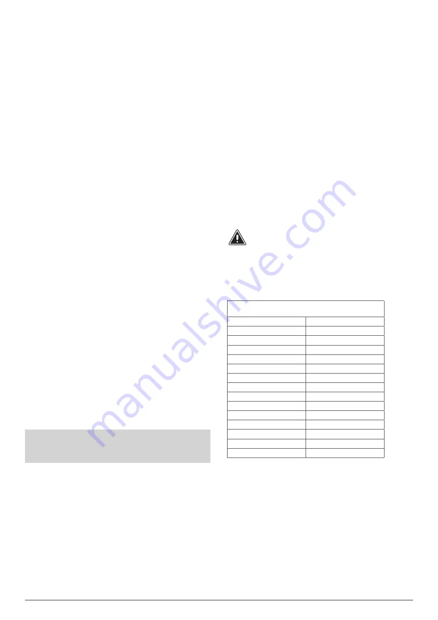
WATER FEATURES
System: Chiller with plate heat exchanger
PH
7.5-9
Electric conductivity
10-500μS/cm
Total hardness
4.5-8.5°dH
Temperature
< 65°C
Oxygen content
< 0.1 ppm
Max. glycol amount
50%
Phosphates (PO4)
< 2ppm
Manganese (Mn)
< 0.05 ppm
Iron (Fe)
< 0.3 ppm
Alkalinity (HCO3)
70 - 300 ppm
Chloride ions (Cl-)
< 50 ppm
Sulphate ions (SO4)
< 50 ppm
Sulphide ion (S)
none
Ammonium ions (NH4)
none
Silica (SiO2)
< 30ppm
ATTENTION! IT IS MANDATORY to install the flow switch and the
water filter, in the hydraulic circuit upstream of the each heat
exchanger. THE LACK OF INSTALLATION OF THESE COMPONENTS
INVALIDATES THE WARRANTY.
Summary of Contents for NYB
Page 2: ......