background image

4

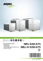
NRL 0280-0750 60Hz

EN

1. 

Description and choce of unit

 ........................................................... 5

2. 

Check list ........................................................................................... 5

3. 

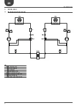
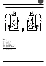
Cooling circuit ................................................................................... 6

3.1. 

NRL cooling circuit only cooling ........................................................ 6

3.2. 

NRL cooling circuit heat pump .......................................................... 7

4. 

Selection and place of installation

 .................................................... 8

4.1. 

Minimum technical ........................................................................... 8

5. 

Positioning

 ........................................................................................ 8

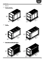
6. Dimension ......................................................................................... 9

6.1. 

NRL 0280 E / NRL 0280 HE ............................................................... 9

6.2. 

NRL 0300 E ....................................................................................... 9

6.3. 

NRL 0330 - 0350 E / NRL 0300 - 0330 - 0350 HE

 .............................. 9

6.5. 

NRL 0500 - 0550 A /  NRL 0500 - 0550 HA

 ..................................... 10

6.6. 

NRL 0600 - 0650 - 0700 A / 0600 - 0650 - 0700 HA

 ........................ 10

6.7. 

NRL 0750 A ..................................................................................... 10

6.8. 

NRL 0750 HA .................................................................................. 10

7. 

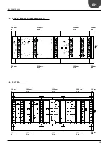
Antivibration positioning

................................................................. 11

7.1. 

NRL 0280 E / NRL 0280 HE ............................................................. 11

7.2. 

NRL 0300 E ..................................................................................... 11

7.3. 

NRL 0330 - 0350 E / NRL 0300 - 0330 - 0350 HE

 ............................ 11

7.4. 

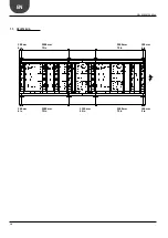
NRL 0500 - 0550 A /  NRL 0500 - 0550 HA

 ..................................... 12

7.5. 

NRL 0600 - 0650 - 0700 A / 0600 - 0650 - 0700 HA

 ........................ 13

7.6. 

NRL 0750 A ..................................................................................... 13

7.7. 

NRL 0750 HA .................................................................................. 14

8. 

CRATE: special wood cover for transport (accessory) .................... 15

9. 

Hydraulic connection

 ...................................................................... 16

9.1. 

Hydraulic connection 

NRL 0280-0700  ........................................... 16

9.2. 

Hydraulic connection 

NRL 0750 ...................................................... 17

10. 

Distribution of percentage weights on supportingpoints

 ............... 18

11. 

Hydraulic circuit .............................................................................. 22

11.1. 

Internal and external hydraulic circuit [NRL HA] "00" (standard) ... 22

11.2. 

Internal and external  hydraulic circuit - NRL pump version ........... 23

11.3. 

Internal and external hydraulic circuit -


NRL pump version and storage tank ............................................... 24

12. 

Electrical data NRL cooling only ...................................................... 26

13. 

Electrical data NRL heat pump ....................................................... 28

14. 

Electronic control (PCO5) ............................................................... 30

15. 

User interface (PGD1) ..................................................................... 32

16. 

Start-up procedure .......................................................................... 33

17. 

Menu structure and navigation

 ....................................................... 34

18. 

User operating procedures

 ............................................................. 35

Summary of Contents for NRL0280E

Page 1: ...5 NRL H 028 075 CHILLER REVERSIBLE HEAT PUMP EXTERNAL UNIT HIGH EFFICENCY HOT WATER PRODUCING UP TO 131 F 55 C POWER SUPPLY 60Hz GAS COOLING ONLY AHRI CERTIFICATION INTERTEK CERTIFICATION COOLING AND...

Page 2: ......

Page 3: ...ence and in depth engineering research and it is built using top quality materials and advanced technologies In addition the CE mark guarantees that our appliances fully comply with the requirements o...

Page 4: ...NRL 0500 0550 A NRL 0500 0550 HA 12 7 5 NRL 0600 0650 0700 A 0600 0650 0700 HA 13 7 6 NRL 0750 A 13 7 7 NRL 0750 HA 14 8 CRATE special wood cover for transport accessory 15 9 Hydraulic connection 16...

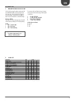
Page 5: ...HEATER 4 T WITH TOTAL RECOVERY Configurations not allowed YD YT YH HT HC TC DC 1 DESCRIPTION AND CHOCE OF UNIT Possibility of production of D H W DCPX_UL VMF ACS AER485 2 CHECK LIST COMPONENTS VERSION...

Page 6: ...E F FILTRO DEIDRATATORE HPS PRESSOSTATO DI ALTA PRESSIONE HPT TRASDUTTORE ALTA PRESSIONE IDL INDICATORE DI LIQUIDO LPT TRASDUTTORE BASSA PRESSIONE KEY BHE EXCHANGER PLATE CN AIR SIDE EXCHANGE CP COMPR...

Page 7: ...BASSA PRESSIONE LS SEPARATORE DI LIQUIDO VIC VALVOLA INVERSIONE CICLO HPT HPS LS VIC VIC LS HPS LPT LPT HPT BHE IDL IDL CP CN CV CV CV CV CV CN TEV TEV F AL F CV CV AL CP CV KEY AL LIQUID TANK BHE EXC...

Page 8: ...L RISK OF DANGER TO A MINIMUM All the staff involved must have thorough knowledge of the operations and any dangers that may arise at the moment in which the installation operations are carried out 4...

Page 9: ...in 1100 mm 43 in 2950 mm 116 in 1750 mm 69 in 3010 mm 119 in 1160 mm 46 in 1606 mm 63 in 1750 mm 69 in 1100 mm 43 in 2950 mm 116 in 3010 mm 119 in 1160 mm 46 in 1606 mm 63 in 1750 mm 69 in 1100 mm 43...

Page 10: ...0750 HA 3010 mm 119 in 1100 mm 43 in 1875 mm 74 in 3070 mm 121 in 1160 mm 46 in 2035 mm 80 in 1990 mm 78 in 4010 mm 158 in 4070 mm 160 in 1100 mm 43 in 1160 mm 46 in 1875 mm 74 in 1975 mm 78 in 1500...

Page 11: ...RL 0280 E NRL 0280 HE 200 mm 8 in 200 mm 8 in 200 mm 8 in 200 mm 8 in 2050 mm 81 in 2050 mm 81 in 7 3 NRL 0330 0350 E NRL 0300 0330 0350 HE 200 mm 8 in 200 mm 8 in 200 mm 8 in 200 mm 8 in 1275 mm 50 i...

Page 12: ...12 NRL 0280 0750 60Hz EN 7 4 NRL 0500 0550 A NRL 0500 0550 HA 200 mm 8 in 1306 mm 51 in 1306 mm 51 in 1306 mm 51 in 1306 mm 51 in 200 mm 8 in 200 mm 8 in 200 mm 8 in...

Page 13: ...0700 HA 7 6 NRL 0750 A 200 mm 8 in 200 mm 8 in 2158 mm 85 in 1440 mm 57 in 2158 mm 85 in 1440 mm 57 in 200 mm 8 in 200 mm 8 in 100 mm 4 in 100 mm 4 in 100 mm 4 in 100 mm 4 in 1500 mm 59 in 1500 mm 59...

Page 14: ...14 NRL 0280 0750 60Hz EN 7 7 NRL 0750 HA 100 mm 4 in 100 mm 4 in 100 mm 4 in 100 mm 4 in 2000 mm 79 in 2000 mm 79 in 2000 mm 79 in 2000 mm 79 in 1150 mm 45 in...

Page 15: ...A E 02 0600 A E 03 0650 A E 03 0700 A E 03 0750 A E 04 NRL MODELS CRATE 0280 HA HE 01 0300 HA HE 02 0330 HA HE 02 0350 HA HE 02 0500 HA HE 02 0550 HA HE 02 0600 HA HE 03 0650 HA HE 03 0700 HA HE 03 07...

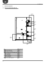
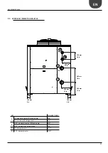
Page 16: ...6 in 428 mm 17 in A B C D F E 9 HYDRAULIC CONNECTION 9 1 HYDRAULIC CONNECTION NRL 0280 0700 KEY CONNECTIONS A IN version with pump 2 B IN standard version 00 2 C OUT standard versions and storage tank...

Page 17: ...mm 10 in 304 mm 12 in 436 mm 17 in 300 mm 12 in 100 mm 4 in 100 mm 4 in A C D B KEY CONNECTIONS A IN standard version 00 and pump 3 IN version with storage tank 4 B OUT standard version 00 and pump 3...

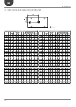
Page 18: ...23 24 VT 13 NRL0550A P1 P3 2161 568 22 36 1317 51 85 27 29 22 23 VT 13 WEIGHT OF RUNNING UNITS NRL TYPE WEIGHT lib CENTER OF GRAVITY PERCENTAGE OF WEIGHT DISTRIBUTION SUPPORTS KIT VT Gxmm Gxin Gy Gyi...

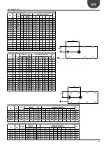
Page 19: ...2 5 0 4 9 34 1 33 7 11 2 11 1 VT 22 NRL0650A 00 2513 545 21 46 1704 67 09 5 7 5 6 33 7 33 1 11 1 10 9 VT 22 NRL0650A 02 04 4101 547 21 54 1971 77 60 0 8 0 7 37 6 37 1 12 0 11 8 VT 22 NRL0650A 01 03 40...

Page 20: ...1 566 22 29 1341 52 81 26 28 22 23 VT 13 NRL0550HA P1 P3 2305 567 22 31 1286 50 63 27 29 21 22 VT 13 WEIGHT OF RUNNING UNITS NRL TYPE WEIGHT lib CENTER OF GRAVITY PERCENTAGE OF WEIGHT DISTRIBUTION SUP...

Page 21: ...33 8 11 7 11 5 VT 22 NRL0650HA 00 2976 543 21 38 1778 70 00 5 0 4 8 34 1 33 2 11 6 11 3 VT 22 NRL0650HA 02 04 4586 545 21 46 1992 78 43 0 6 0 6 37 6 36 9 12 3 12 1 VT 22 NRL0650HA 01 03 4475 545 21 46...

Page 22: ...te SYSTEM SIDE 2 Water filter fitted 3 Flow switch fitted 4 Water temperature probes IN OUT 5 Ball stop drain 6 Air Vent RECOMMENDED COMPONENTS NOT SUPPLIED CHARGED TO THE INSTALLER 6 Air Vent 7 Anti...

Page 23: ...o acqua 3 flussostato 4 sonde temperatura acqua IN OUT 5 rubinetto di scarico 6 valvola di sfiato 8 pompa 10 vaso d espansione 11 vavola di sicurezza bar 14 valvola d intercettazione NON FORNITO CONSI...

Page 24: ...e and the installation of components external to the NRL up to the installer who must ope rate according to the rules of good technical design and in compliance with the regulations in force in the co...

Page 25: ...cannot be considered responsible for any damage caused by the lack of or ine ective appliance earth connection For units with three phase power supply check the correct connection of the phases ATTENT...

Page 26: ...ntation 460 3 60Hz MODELS WITHOUT PUMP LRA A 186 195 191 220 228 265 E 124 153 158 187 MCA A 70 75 90 100 110 125 E 40 50 60 70 MOP A 80 90 100 110 125 125 E 50 60 70 80 MODELS WITH LOW PUMP P1 P2 01...

Page 27: ...00 E 100 110 125 175 MODELS WITH HIGH PUMP P3 P4 03 04 LRA A 382 402 388 463 481 537 E 242 290 304 374 MCA A 150 175 175 225 300 300 E 90 90 110 150 MOP A 175 200 200 250 300 300 E 110 110 125 175 Ali...

Page 28: ...60Hz MODELS WITHOUT PUMP LRA HA 186 195 191 220 228 268 HE 124 154 158 187 MCA HA 70 75 90 100 110 125 HE 40 60 60 70 MOP HA 80 90 100 110 125 125 HE 50 60 70 80 MODELS WITH LOW PUMP P1 P2 01 02 LRA H...

Page 29: ...110 125 175 MODELS WITH HIGH PUMP P3 P4 03 04 LRA HA 382 402 388 463 481 545 HE 242 294 304 374 MCA HA 150 175 175 225 300 300 HE 90 100 110 150 MOP HA 175 200 200 250 300 300 HE 110 125 125 175 Alime...

Page 30: ...tions n 2 Cod Anti freeze alarm See User Manual Restart Manual Elec cal Heater OFF ON Temperature 5 C 4 C Circula ng Pump OFF ON Temperature 5 C 4 C Only for pure water not added with glycol WATER FLO...

Page 31: ...ir Cavo telefonico KIT PGD1 ACCESSORIO S90CONN cavo di collegamento Cavo telefonico External Alarm J15 N08 C8 NC8 Circula ng Pump J12 N01 CP01 Remote Control PGD1 Circula ng Pump J22 N018 CP02 Externa...

Page 32: ...y Displays the list of active and historical alarms red LED on active alarm MENU ACTIVATION key Pressing this key activates the navigation between menus orange LED on winter operating mode active EXIT...

Page 33: ...ge Timeshowmask English ESCtoconfirm 20 A Remaining time for software loading this value shows the remain ing time to starting the software loaded on the unit and passing the to system language select...

Page 34: ...ers are only modi ed by personnel quali ed in the installa on and con gura on of the unit Menu structure and naviga on Index Icon Menu Menu function A MAIN The screens in this menu display the current...

Page 35: ...is possible to move between the screens using the arrow keys the key to move to the previous parameter and the key to move to the next parameter c When the desired parameter is shown press the key to...

Page 36: ...cqua VR Italia Tel 39 0442 633111 Fax 39 0442 93577 marketing aermec com www aermec com Aermec reserves the right to make all modification deemed necessary for improving the product at any time with a...

Reviews: