aerl
COMMS MANUAL
COOLMAX SR
Australian Energy Research Laboratories, Pty.Ltd
AER07.004 – Version G2 v9
13
th
January 2016
18 of 21
Signal PIN Assignment
PIN
Assignment
Type
Functional Description
Isolated
J1-1
GND
Analogue input
Temperature compensation thermistor
NO
J1-2
TMPCMP
J1-3
GND
Digital input
Pull these lines together to disable
output of the Maximizer
NO
J1-4
ON/OFF
J1-5
Alarm NO
Clean contact
output
Will close when an alarm is active
YES - 1000V
J1-6
Alarm COM
J2-1
PV IN-
PV PWR IN
Refer to Product datasheet for the
current and voltage limitations
NO
J2-2
PV IN+
J2-3
BATT OUT +
BATT PWR OUT
Refer to Product datasheet for the
current and voltage limitations
NO
J2-4
BATT OUT -
J3-1
CAN +12V
Output power
Power for the CAN bus
YES
J3-2
CAN GND
J3-3
SHIELD
YES
J3-4
CAN H
Digital IO
CAN signals
J3-5
CAN L
J3-6
NC
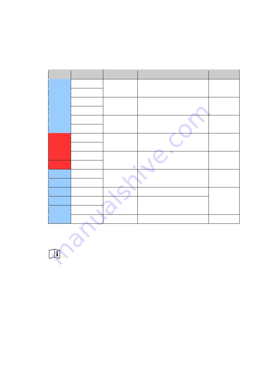
Table 1 - Signal PIN Assignment
4.3 SHIELDING
Correct shielding practice is important for error free communications. Incorrect shielding can cause
more interference than unshielded cables would experience. Shields should be linked between
each wire segment along the network but only grounded in one place. The following paragraphs
explain how to achieve this.
The shield should be wired through the entire network independently of the ground and connected
to ground at the end of the network and nowhere else in the network. This is shown at the right
hand end of the example network in
Figure 6.
4.4 CAN TERMINATION
A 120 Ω resistor needs to be wired between the CAN-H and CAN-L lines at either end of the linear
network in order to terminate both ends of the network. At the far end of the network the resistor can
be simply installed into the last terminal block.
Important


