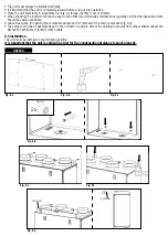
fig. 5.j
Spirit level
fig. 5.k
2x
Spacers
H=min. 60mm
fig. 5.h
fig. 5.i
Ø125mm Ø125mm
5.a
Prepare the surface where the unit is to be mounted. Make sure that the surface is flat, levelled and that it supports the
weight of the unit. Perform the installation in accordance with local rules and regulations.
5.b
Drill the holes in the wall.
5.c
Use appropriate wall plugs and screws (not supplied).
5.d
Fix the 2 spacers on the back of the unit.
5.e
Hang the unit to the wall by means of the fixing brackets.
5.f
Screw safely.
5.g
Make sure that the unit is at spirit level.
5.h
Connect the condensation drain joints (G 3/4” M) placed in the bottom side of the unit to a U-bend (or similar) on the
condensation drainage pipe. In case close the non-used joint by means of the supplied drain stopper. Make sure this
operation is well done in accordance to the best practice in order to assure water and air tightness.
5.i
Connect the unit to the duct system. Make sure that all necessary accessories are used to create a functional ventilation
solution.
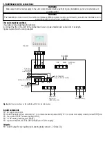
Connect the unit electrically according to § 5.4. Check that it starts up correctly.
QR400A - QR550A
Summary of Contents for QR280A
Page 1: ...QR280A QR400A QR550A aL ...


