background image

13

6. Technical specifications

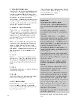
Eingänge Kanäle 1 und 2 

Switchable microphone or line input Combo socket,  

XLR and 1⁄4“ jack (6.35 mm) 

line mode (jack input)


Unbalanced high impedance input for 

instrument pick-ups and line-level sources  

Gain adjustment range: +3...+20 dB 

Min. input voltage: 100 mV (–20 dBV) 

Max. input voltage: 3 V (+10 dBV) 

Input impedance: 2.2 MΩ|| 60 pF Signal-to-noise ratio, 

A-weighted 

Min. gain: 108 dB

Max. gain: 98 dB 

Frequency response: 20 Hz...20 kHz / Ω  

1 dB THD + N (1 kHz): < 0.3%

mic mode (XLR input) 

Balanced microphone input 

1 = ground, 2 = positive (+), 3 = negative (–)  

Gain adjustment range: +4...+40 dB 

Min. input voltage: 10 mV (–40 dBV) 

Max. input voltage: 3 V (+10 dBV) 

Input impedance: 2.1 kΩ 

Unbalanced:1.1 kΩ Signal-to-noise ratio, A-weighted 

Min. gain: 108 dB 

Max. gain: 93 dB 

Frequency response: 20 Hz...20 kHz / Ω 

1 dB THD + N (1 kHz): < 0.1% 

Phantom power: 24 V, R = 1.2 kΩ per terminal, switchable 

for each channel, total current max. 10 mA per channel, 

short circuit protected 

Warning: 

External equipment may be damaged by  

inappropriate use of phantom power. In case of doubt 

keep the 24 V phantom power switch off (not pushed).

Clip indicator 

Red LED 

Headroom: 8 dB

aux in 

Auxiliary stereo input (mono-mixed), e.g. for 

CD player Cinch (RCA) sockets (left / right)  

and 3.5 mm stereo jack socket. 

Level control 

Min. input voltage: 2 x 250 mV (–14 dBV) Max. input 

voltage: 2 x 10 V (+20 dBV) Input impedance: 10 kΩ

Outputs, Line out


Unbalanced line output after master Mono jack,  

1⁄4” (6.35 mm) 

Nominal output voltage: 1 V (0 dBV)  

Max. output voltage: 9 V (+19 dBV)  

Output impedance: 47 Ω 

Min. load impedance: 2 kΩ 

Residual noise (

master fully anticlockwise

): 

A-weighted: 1 μV (–120 dBV)

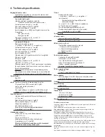
 Headphones output


Stereo jack, 1⁄4” (6.35 mm) Output power, 

1 kHz, THD = 1%: 

Typ. 2 x 40 mW / 32 Ω 

Residual noise (master fully anticlockwise): 

A-weighted: 3.3 μV (–110 dBV) 

Warning: Suitable for headphones with stereo jack 

only. Do not connect any mono jacks.

DI-out 

Balanced XLR output 

1 = ground, 2 = positive (+), 3 = negative (–)


Level control


Nominal output voltage (differential), 

adjustment range: 

41...410 mV (–28...–8 dBV) Output impedance: 

47 Ω each terminal to ground 

Min. load impedance (differential): 1 kΩ 

Residual noise (both channels in line mode), 

A-weighted: 3.3 μV (–110 dBV)

Tone controls
channel 1 and 2 

low±12 dB at 100 Hz (shelf type) 
high ±13 dB at 10 kHz (shelf type)

Effects

 (built-in effects) 

Digital effect processor with 4 presets 

 1 = Reverb with short predelay 

2 = Reverb with long predelay 

3 = Repeating delay 

4 = Chorus

Footswitch connector


Connector for a dual footswitch 

Stereo jack, 1⁄4” (6.35 mm) 

Tip = footswitch for muting channel 1  

Ring = footswitch for muting channel 2  

Sleeve = ground (common) 

Function: Switch ON = channel muted

Power supply voltage


24V=0,5 A 

Use only supplied mains adapter.

Mains adapter 

Mains voltage: 100-240 V~Power consumption when 

used with 

Dual

 mix 2: max. 10 W

General
Metal housing


Aluminium

Finish

  Anodized black

Dimensions


  65 mm (2.56") high 

105 mm (4.13") weide 

135 mm (5.31") deep

Weight:

  480 g (1.06")

Definitions and conditions


Input and output voltages are RMS values for a sine signal and 1 kHz unless 

stated otherwise.  

Tone controls 

in neutral position unless stated otherwise.  

Min. input voltage:

 Input voltage for nominal output voltage at line out 

with gain and master fully clockwise.  

Max. input voltage: 

Permissible input voltage that does not cause dis-

tortion more than the rated THD + N (assuming suitable control settings). 

Signal-to-noise ratio (SNR):

 Ratio of nominal output voltage to noise 

voltage at line out, at specified gain setting, master fully clockwise, input 

shorted, 20 Hz...20 kHz.  

Note:

 The SNR found at line out may be less than the SNRs specified for the 

channels because both channels contribute to the output noise.  

Residual noise: 

Noise voltage at an output when all gain and level settings 

are minimal.  

THD + N: 

Total harmonic dist noise for nominal output voltage at 

line out.  

Specifications and appearance subject to change without notice.

Summary of Contents for Dual mix 2

Page 1: ...1 Dual mix 2 Bedienungsanleitung UserManual 01 2017 ...

Page 2: ...reude haben Der dual mix 2 ist ein hochwertiger zweikanaliger Vorverstär ker für Instrument Line oder Mikrofonsignale Das Gerät ist wie ein kleines Mischpult mit einfachen effektiven Merkmalen aus gestattet zwei Eingänge für je ein Mikrofon oder Instrument und Line Signal mit zuschaltbarer 24V Phantom Spannung ein aktives Zweiband Klangfilternetzwerk pro Eingang ein vierfacher Multi Effekt mit zwe...

Page 3: ...ich und Reparatur qualifziertem Fachpersonal Im Fall eines Fremdeingriffs erlischt die 2 jährige Garantie 13 Für die Einhaltung der EMV Forderung müssen geschirmte Kabel mit korrekt angeschlossenen Steckverbindern für alle Signalanschlüsse verwen det werden 14 Verwenden Sie immer einen geerdeten Netz anschluß mit der richtigen Netzspannung Falls Sie Zweifel haben ob der Anschluß geerdet ist lassen...

Page 4: ...2 via Fußschalter line out Signalausgang 6 3 mm Mono Klinken Buchse DI out Signalausgang symmetrisch XLR Buchse DI level DI out Signalpegel Regler Frontseite channel 1 Signaleingang Kombibuchse für 6 3 mm Mono Klinkenstecker und XLR Stecker channel 2 Signaleingang Kombibuchse für 6 3 mm Mono Klinkenstecker und XLR Stecker hp filter Schalter zur Aktivierung des Hochpass Filters siehe Grafik und Tex...

Page 5: ... Aussteuern Richtig ausgesteuert bedeutet dass der Signalpegel Lautstärke in einem Gerät oder mehreren Geräten einer Signalkette weder zu hoch noch zu niedrig ist Das gilt auch für alle Baugruppen eines Gerätes gleichermaßen hier z B high und low Es muss also sichergestellt werden dass kein Schaltungsteil über steuert wird und dadurch z B ein Gerät überlastet wird oder dem Signal ungewollt Verzerr...

Page 6: ...deren unsymmetrischer Line Ausgang durch einen XLR Stecker modifiziert worden ist Bei Unsicherheit erkundigen Sie sich bitte beim Hersteller des von Ihnen verwendeten Gerätes 5 1 2 Zweiband Klangregelung Die Zweiband Klangregelung Ihres dual mix 2 ist eine aktive und hochwertige Klangbeeinflussung die den natürlichen Ton von Instrumenten und Stimme erhält und Ihnen die Möglichkeit zur gezielten Ak...

Page 7: ... any mono jacks DI out Balanced XLR output 1 ground 2 positive 3 negative Level control Nominal output voltage differential adjustment range 41 410 mV 28 8 dBV Output impedance 47 Ω each terminal to ground Min load impedance differential 1 kΩ Residual noise both channels in line mode A weighted 3 3 μV 110 dBV Tone controls channel 1 and 2 low 12 dB at 100 Hz shelf type high 13 dB at 10 kHz shelf t...

Page 8: ...t can be Please take a moment to read this brief manual We want you to understand how our product works and what it can do for you We want you to gain benefit from its many features but most of all we want you to ENJOY it The dual mix is a high quality two channel preamplifier for instrument line or microphone signals The unit offers simple efficient features just like a small mixing console two i...

Page 9: ...3 In keeping with the EMV regulations screened cables with correctly fitted connectors must be used for all signal connections 14 Always use an earthed power supply with the correct mains voltage If you are in doubt about the power outlet ground have it checked by a qualified technician 15 Cable up your amp only when it is powered off 16 This device should be installed near the socket out let and ...

Page 10: ...r socket 24 Volt DC mute jack socket for a footswitch to mute ch 1 and or ch 2 line out signal output 6 3 mm mono jack socket DI out signal output symmetrical XLR socket DI level DI out signal level control Front side channel 1 signal input combo socket for 6 3 mm mono jackplug and XLR connector channel 2 signal input combo socket for 6 3 mm mono jackplug and XLR connector hp filter on off switch ...

Page 11: ...tch the amplifier on The green power control LED indicates operational readiness 4 2 Adjustment Note Level adjustment By setting the level correctly we mean the signal level in one or several devices in a signal chain is neither too high nor too low This applies equally to all circuits in a complete circuit design EQs preamps etc Consequently care must be taken that no part of the circuit is overl...

Page 12: ...you are using 5 1 2 Dual band Equalization The dual band equalizer of your dual mix provides you with an active and high quality sound interac tion tool that supports the natural tone of instru ments and voice whilst simultaneously offering you the possibility of a controlled interaction With all controls in mid position the filters are set to produce a very pleasing and natural sound impres sion ...

Page 13: ...nnect any mono jacks DI out Balanced XLR output 1 ground 2 positive 3 negative Level control Nominal output voltage differential adjustment range 41 410 mV 28 8 dBV Output impedance 47 Ω each terminal to ground Min load impedance differential 1 kΩ Residual noise both channels in line mode A weighted 3 3 μV 110 dBV Tone controls channel 1 and 2 low 12 dB at 100 Hz shelf type high 13 dB at 10 kHz sh...

Page 14: ... aer amplifier gmbh Haberstrasse 46 D 42551 Velbert info aer amplifier com Sales Africa America Asia Oceania aer music gmbh Haberstrasse 46 D 42551 Velbert info aer music de Sales Europe www aer music de ...

Reviews: