BC 2000
DIGITAL
Audio Routing, Mixing and Processing System for Program Production Centers
HARDWARE MANUAL
50
3.20. BC2215. E1/T1/J1 communications module.
General description.
The BC2215 board allows you to manage an standard E1, J1 o T1 link to transmit and receive
audio channels (linear or encoded) and/or data channel.
This board is inserted into the rear part of the BC2000DF rack.
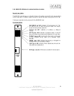
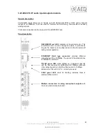
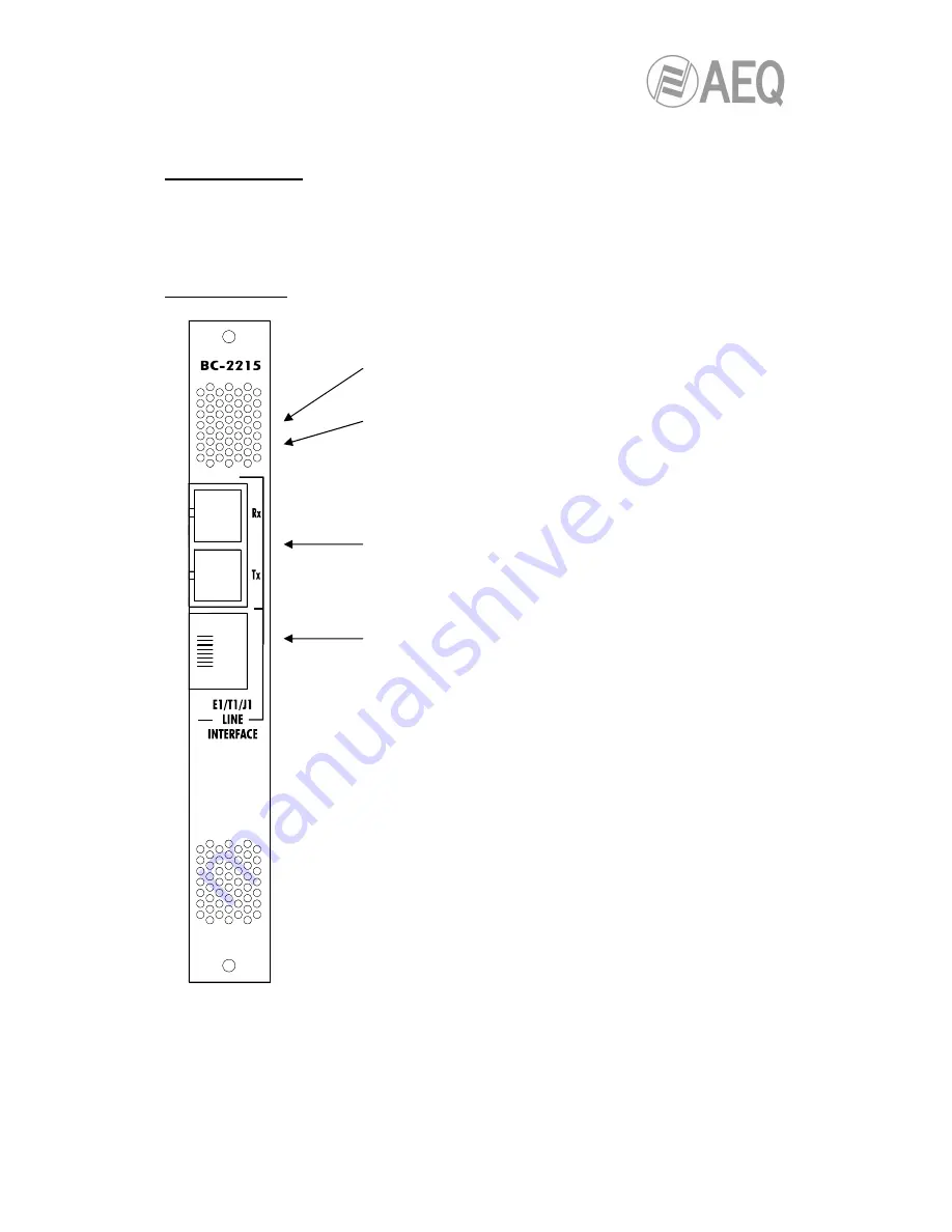
Panel description.
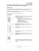
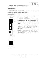
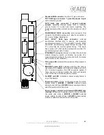
'HW ERROR' red LED (right): indication of board start error.
This LED will turn on when the system starts, and should
remain off during normal operation.
'COMM ERROR' red LED (left): indicates an error on
communications link. When it blinks it’s a logic type error
(synchronization, wrong framing…) and when it remains on
it’s a physical type error (short-circuit, open circuit, low
signal…).
SC 'Rx' and 'Tx' connectors: FDDI PMD optical fiber
interface with a range of 2000 meters (if your installation
entails a range greater than 2000 meters, contact our sales
department).
RJ48 type connector: twisted pair cable interface with
software configurable impedance: 120 / 75 ohms for E1 and
100 ohms for J1 and T1.

