BC 2000
DIGITAL
Audio Routing, Mixing and Processing System for Program Production Centers
HARDWARE MANUAL
25
Other characteristics and features.
-
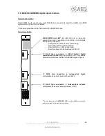
Internal warning signal indicating a failure in one of the power supplies. If a failure occurs, the
“ALARM” LED on the BC2240 controller board will light up.
-
Power feed circuit designed to support hot-swapping operations.
-
Digital adjustment of analog gain (±12 dB) in the 4 outputs.
-
Digital adjustment of digital gain (±12 dB) in the 4 outputs.
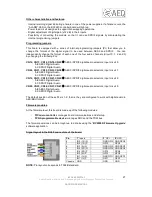
Programming jumpers.
This board has a series of internal programming jumpers (PJ). However, these jumpers are
configured at the factory and, in normal operation, do not need to be changed.
Firmware modules.
At the firmware level, this board is made up of the following modules:
-
PIC microcontroller: manages board communications and start-up.
-
FPGA programmable device: manages the converters and the TDM bus.
The firmware versions can be brought up to date by using the “BC2000D Firmware Upgrade”
software application.
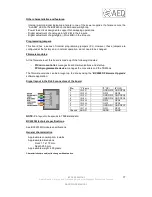
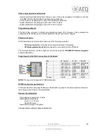
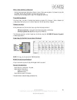
Signal layout in the RJ45 connectors of the board.
NOTE: Pin layout corresponds to T568B standard.
BC2205 technical specifications.
This board has the same specifications as the BC2201, except for the characteristics relative to
the analog inputs that are not implemented.
General characteristics.
-
Approximate consumption: 9 watts.
-
Approximate dimensions:
Front: 17 x 172 mm.
Depth: 255 mm.
-
Approximate weight: 300 grams.
Characteristics are subject to change without notice.
Pin
-
'2' Outputs
'3' GPI
'4' GPO
8
-
OUT 2 (1R) V-
GND GPI2 GND GPO2
7
-
OUT 2 (1R) V+ GPI2
GPO2
6
-
OUT 3 (2L) V-
GND GPI3 GND GPO3
5
-
OUT 4 (2R) V-
GND GPI4 GND GPO4
4
-
OUT 4 (2R) V+ GPI4
GPO4
3
-
OUT 3 (2L) V+ GPI3
GPO3
2
-
OUT 1 (1L) V-
GND GPI1 GND GPO1
1
-
OUT 1 (1L) V+ GPI1
GPO1
Chassis
-
AGND
AGND
AGND


