background image

OUT1 ? Output for load 1

OUT2 ? Output for load 2

S1 ? External switch control for load 1

S2 ? External switch control for load 2

1. Shut off the main circuit breaker of your home for safety during the installation and ensure the wires are not short circuited during the installation which will

cause damage to the Nano Switch.

Note: Your home?s main circuit breaker must support the overload protection for safety.

2. Preparing connection wires 14 AWG power wires for Input/ Output. 18 AWG copper wires for external manual switch. Use the wire stripper cut the metallic part

of the connection wire and make sure the length of the metallic part is about 5mm.

Note: All connection wires needs to be flexible cable.

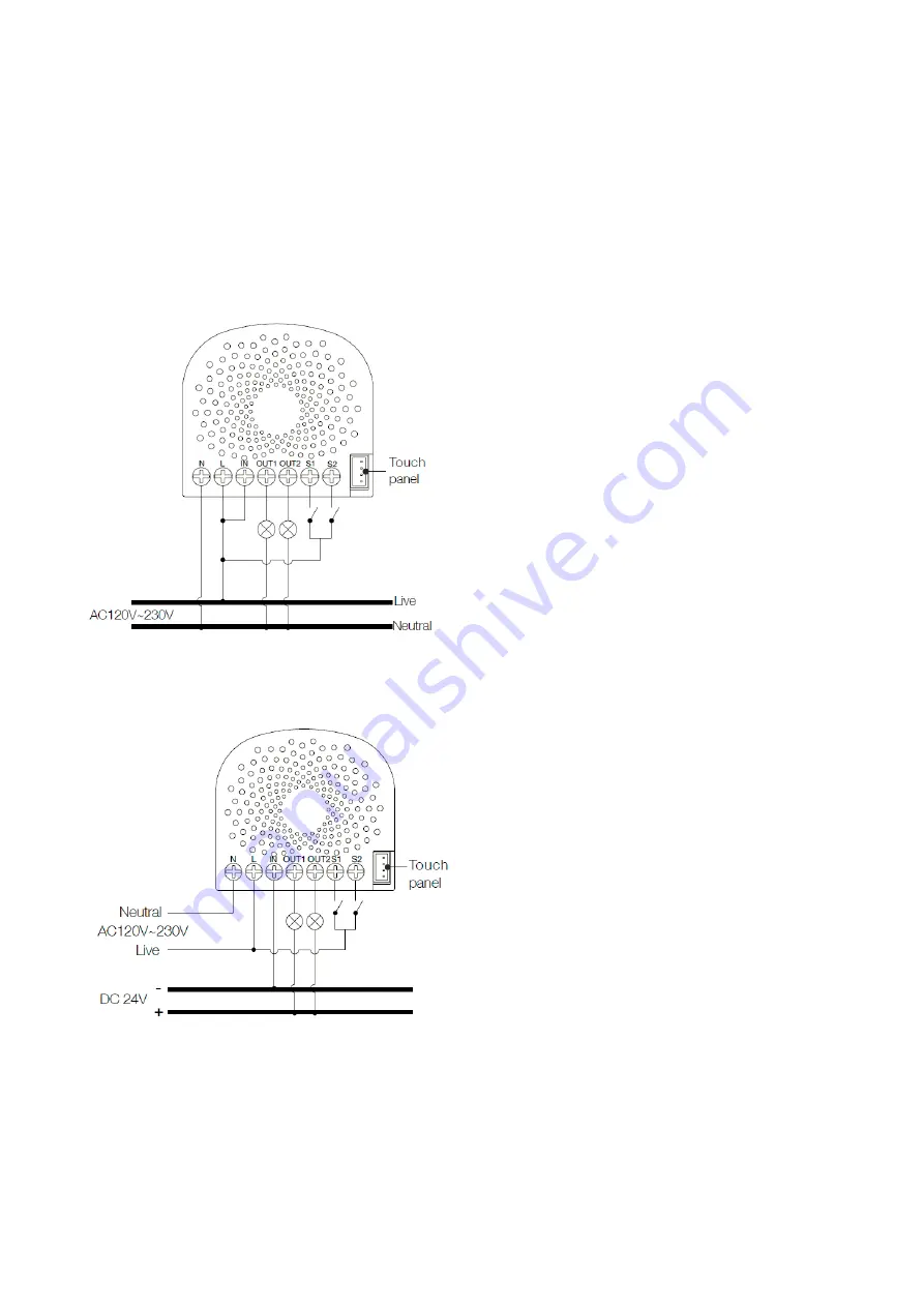
Wiring diagram of AC120V/230V power input.

In some cases, you may have some loads just only can be used on the voltage of DC24V and hope that it still can be controlled by the Nano Switch, so please

refer to the following diagram to achieve this:

Note: The ?IN? terminal should be connected to the ?-? of DC 24V input.

Wiring diagram of DC24V power input.

Since the Nano Switch also supports the DC24V power input, so you can use it to control the loads that powered by DC24V.

Summary of Contents for AEOEZW116

Page 1: ...other nodes meshed network in case the receiver is not in direct wireless range of the transmitter This device and every other certified Z Wave device can be used together with any other certified Z W...

Page 2: ...ery device is excluded properly from this network Reset to factory default This device also allows to be reset without any involvement of a Z Wave controller This procedure should only be used when th...

Page 3: ...pper wires for external manual switch Use the wire stripper cut the metallic part of the connection wire and make sure the length of the metallic part is about 5mm Note All connection wires needs to b...

Page 4: ...V power wire All above wiring diagrams show that the Nano Switch uses 2 Way or momentary button switches as the external manual switch for 2 Way connection The below diagram will show you that the Nan...

Page 5: ...r device Z Wave devices control other Z Wave devices The relationship between one device controlling another device is called association In order to control a different device the controlling device...

Page 6: ...atus 1 Always on 2 Always off Parameter 80 To set which notification would be sent to the associated devices Group 1 To set which notification would be sent to the associated devices Group 1 when the...

Page 7: ...ter 87 Set appointment 2 Set appointment 2 Size 4 Byte Default Value 2293760 Setting Description 0 60 The minute value of ON time 256 316 The hour value of ON time 65536 65543 The day value Mon to Sun...

Page 8: ...t group 3 To set which reports need to be sent in Report group 3 Size 1 Byte Default Value 0 Setting Description 1 Send Meter Report of voltage V 2 Send Meter Report of current A 4 Send Meter Report o...

Page 9: ...ay switch mode 3 2 state switch mode Parameter 122 Set the control destination for external switch S1 Set the control destination of the external switch Size 1 Byte Default Value 3 Setting Description...

Page 10: ...Activation Scene Actuator Conf Meter Association Grp Info Device Reset Locally Zwaveplus Info Configuration Alarm Manufacturer Specific Powerlevel Firmware Update Md Clock Association Version Hail Co...

Page 11: ...issued by a Z Wave device to announces that is able to communicate Node Information Frame is a special wireless message issued by a Z Wave device to announce its capabilities and functions c 2021 Z Wa...

Reviews: