


ROUT
ING
BY
F
REE
HAN
D
(FIG.
15
)
When used freehand, your plunge router becomes a
flexible and versatile tool. This flexibility makes it possible
to easily rout
e
signs, relief sculptures, etc.
There are two basic techniques for freehand routing:
Routing letters, grooves, and patterns into wood.
Routing out the background, leaving the letters or
pattern raised above the surface.
When
freehand
routing,
we
suggest
the
following:
Draw or layout the pattern on workpiece.
Choose the appropriate cutter.
N
OTE
:
A core box or V-groove bit is often used for
routing letters and engraving objects. Straight bits
and ball mills are often used to make relief carvings.
Veining bits are used to carve small, intricate details.
Rout
e
the pattern in two or more passes. Make the
first pass at 25% of the desired depth of cut. This
process will provide better control as well as being a
guide for the next pass.
D
o
not
rout
e
deeper than 1/8 in. (3.2 mm) per pass
or cut.
Follow
these
directions
when
routing
by
freehand:
Choose the appropriate cutter, set desired depth of
cut, carefully check set-up, and secure workpiece.
Make a test cut in a scrap piece of wood from the
same workpiece if possible.
Several cuts that require repositioning of router may
be needed for a particular job. If this situation exists,
unlock plunge lock lever to raise cutter inside router
subbase after each cut, reposition router for next cut,
gradually plunge cutter into workpiece until stop bar
contacts depth stop, lock plunge lock lever and
continue routing.
After all cuts have been made, unlock plunge lock
lever, raise cutter inside router subbase, remove
router from workpiece, turn off the router, and allow
cutter to come to a complete stop.
ROUT
ING
ED
G
ES
Place router on workpiece, making sure the router bit
does not contact workpiece. Turn router on and let the
motor build to its full speed. Begin your cut, gradually
feeding cutter into workpiece.
Upon completion of cut, turn motor off and let it come to
a complete stop before removing router from work
surface.
Unlock plunge lock lever to raise cutter from any
preset depth of cut. This also permits raising cutter
inside router subbase.
Place router on workpiece inside pattern to be routed.
Grasp handles securely and press the switch to start
your router.
Let motor build to full speed, then gradually plunge
cutter into workpiece until stop bar comes into contact
with depth stop.
Lock plunge lock lever to secure depth of cut setting.
Begin routing out the pattern, continuing until a
complete pass at this depth of cut has been made.
WA
R
NING:
Do not use large router bits for freehand routing. Use
of large router bits when freehand routing could cause
loss of control or create other hazardous conditions
that could cause possible serious personal injury.
Keep a firm grip on router with both hands at all
times. Failure to do so could result in loss of control
leading to possible serious injury.
WA
R
NING:
WA
R
NING:
Never pull router out of work and place upside down
on work surface before the cutter stops.
Connecting a dust extractor (Fig. 16).
Mount the dust port (29) on the router base (16) with
screws. The dust extractor hose can be connected
to the dust extraction channel.
-
12
-
OPER
A
T
I
O
N
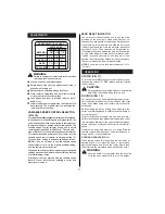
When routing a groove wider than the diameter of the
cutter, clamp a straightedge on both sides of the cutlines.
Position both guides parallel to the desired line of cut and
spaced equal distances from the desired edges of the
groove. Rout
e
along one guide; then, reverse direction
and rout
e
along the other guide. Clean out any remaining
waste in the center of the groove freehand.
When routing straight cuts across stock, clamp a straight
edge to the workpiece to use as a guide. Position the
straightedge parallel to the line of cut and offset the
distance between the cutting edge of the cutter and the
edge of the router base. Hold the router base against the
straightedge and rout
e
the groove.
Insert the parallel guide (20) into the hole of the Router
base (16).
Draw a cutting line on the word-piece (28).
Lower the router body until the cutter is in contact
with the work-piece.
Tighten the parallel guide lock knob (6).
Postion the route on the cutting line. The outer cutting
edge of the cutter must coincide with the cutting line.
FI
TT
ING
AN
D
A
DJUST
ING
T
H
E S
HIF
T
ING
B
E
A
R
ING
(FIG.
1
4)
Summary of Contents for RT 1350 E
Page 1: ...Instructions for use RT 1350 E ...
Page 3: ... 3 TO SPEED TO SPEED Fig 7 Fig 8 Fig 9 Fig 10 Fig 12 9 10 8 10 9 12 11 2 1 Fig 11 ...
Page 5: ... 5 Fig 20 Fig 21 Fig 22 T L Fig 23 36 ...
Page 14: ......
Page 15: ......
Page 16: ...w w w a e g p t c o m AEG Elektrowerkzeuge Max Eyth Straße 10 D 71364 Winnenden Germany ...


