


WA
R
NING:
WA
R
NING:
Lock (L) plunge lock lever to position cutter at "zero"
depth of cut.
Adjust hex nuts until they come in contact with stop
flange (27). This will provide a position stop at “zero”
depth of cut.
Make sure the hex nuts are securely tightened against
each other.
Rotate depth stop knob (8) to desired position, loosen lock
knob (10) and adjust stop bar (9) until it touches depth stop.
Slide zero-reset indicator (11) up or down the scale (12) on
stop bar until red line on zero-reset indicator aligns
with a desired reference point. For example, align
red line with 25mm mark on the scale.
Lift stop bar to obtain desired depth of cut. For
example, if setting 3.5 mm depth of cut, the
zero-reset indicator will move 3.5mm from
the 25mm reference point.
Tighten lock knob securely.
Position your router so that the cutter can extend
below the subbase for desired depth setting.
Unlock plunge lock lever.
Grasp handles and lower router until stop bar con-
tacts depth stop.
Lock plunge lock lever to position cutter at desired
depth of cut.
DEPT
H
STOP
(FIG.
8 & 9
)
The depth stop is located on the base of your router and
makes it possible to make deep or heavy cuts in
successive passes by use of the Adjustable Depth
Stop System. Alignment marks make depth of cut
changes quick and easy.
A preset cutting depth is achieved by plunging router
until stop bar comes in contact with depth stop. The
micro-adjusting feature provides alignment marks at
each 90
°
rotation of the depth stop knob. Each 90
°
rotation of the knob changes depth of cut setting 1/64 in.
(0.4 mm).
Acomplete rotation (360
°
) of the depth stop knob changes
the depth of cut setting 1/16 in. (1.6 mm).
The Adjustable Depth Stop System provides for depth of
cut changes to be made from 0 to 1/2 in. (12.7 mm) from
the initial setting of the stop bar.
This initial setting of the stop bar can be "zero" depth of
cut, or it can be any depth of cut setting that you choose
as a starting point for a particular job to be performed.
TO SET DEPT
H
STOP
U
N
PLU
G
Y
OUR ROUTER
.
WA
R
NING:
Always wear safetey goggles or safety glasses with
side shields when using your router. Failure to do so
could result in dust, shavings, chips, loose particles,
or foreign objects being thrown in your eyes result-
ing in possible serious injury. If the operation is
dusty, also wear a face or dust mask.
-
10
-
A
DJUST
M
E
N
TS
DEPT
H
O
F
C
UT
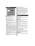
When routing a groove that is too deep to safely cut in
one pass, it is best to make the cut in several passes. We
recommend that cuts be made at a depth not exceeding
1/8 in. (3.2 mm) and that several passes be made to
reach deeper cuts.
Proper depth of cut depends on several factors:
horsepower of router motor, type of cutter being used,
and type of wood being routed. A lightweight, low
horsepower router is designed for making shallow cuts.
A router with high horsepower rating can safely cut
deeper. For example: small bits (26), such as veining bits with
1/16 in. (1.6mm) cutting diameters, are designed to remove only
small amounts of wood. Large bits, such as straight-flute
bits, are made to remove larger amounts of wood in a
single pass. Cuts can be made deeper in soft woods,
such as white pine, than in tough hardwoods, like oak or
maple. Based upon these considerations, choose a
depth of cut that will not place excessive strain on router
motor. If you find that extra force is needed or that the
motor speed slows down considerably, turn off router
and reduce the depth of cut. Then, make the cut in two
or more passes.
TO
A
DJUST DEPT
H
O
F
C
UT
(FIG.
5
-
7
)
U
N
PLU
G
Y
OUR ROUTER
.
Do not use cutters with undersized shanks. Under-
sized shanks will not tighten properly and could be
thrown from the tool causing injury.
Do not use cutters that are larger in diameter than
the opening in router base. Use of such cutters will
come in contact with the router base and damage
both the cutter and router base. This situation could
also cause possible loss of control or create other
hazardous conditions that could cause possible seri-
ous personal injury.
Failure to unplug your router could result in acciden-
tal starting causing serious injury.
Raise cutter by unlocking (U) plunge lock lever (14).
Adjust hex nuts (21) on threaded post (24) until cutter is
inside router subbase (17).
Place router on a flat surface.
Lower router until tip of cutter barely touches flat
surface.
WA
R
NING:
Summary of Contents for RT 1350 E
Page 1: ...Instructions for use RT 1350 E ...
Page 3: ... 3 TO SPEED TO SPEED Fig 7 Fig 8 Fig 9 Fig 10 Fig 12 9 10 8 10 9 12 11 2 1 Fig 11 ...
Page 5: ... 5 Fig 20 Fig 21 Fig 22 T L Fig 23 36 ...
Page 14: ......
Page 15: ......
Page 16: ...w w w a e g p t c o m AEG Elektrowerkzeuge Max Eyth Straße 10 D 71364 Winnenden Germany ...


