


Protect 5.31/xxx-480-220-120 10 kVA - 120 kVA
Page 29 of 56
8000020680 BAL, en
6.4
Connection Cross Sections and Fuse Protection
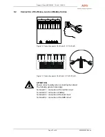
Layout of cross sections in acc. with
DIN 0298, Part 4, Table 3
Type rating in kVA
Laying
type
B1/B2
10 20 30 40 60 80
100
120
1 Rectifiers, input
X1
Rectifier fusing in A
20
40
63
80
125
160
200
250
2 Cross section in mm²/pole *1 min.
max
10
2x95
10
2x95
16
2x95
25
2x95
50
2x95
70
2x240
95
2x185
2x50
2x185
3 SBS circuit input
X4
SBS fusing in A
125
250
315
400
630
800
1000
1250
4 Cross section in mm²/pole *1 min.
max
35
2x95
70
2x95
2x50
2x95
2x70
2x95
4x50
4x95
3x120
3x240
4x150
4x240
5 Load output
X3
Load output fusing in A
max.
40
63
100
125
200
250
315
400
6 Cross section in mm²/pole
min.
max.
35
2x95
95
2x95
2x70
2x95
2x95
2x95
2x150
4x95
3x120
3x240
4x150
4x240
7 Remote signalling
X12
Cross section of the signal line
in mm²/pole
max..
0,2 - 2,5
Battery
8 Battery connection
X2
Battery fusing in A
50
100
160
200
315
400
9 Cross section in mm²/pole
min.
max.
10
2x95
25
2x95
50
2x95
95
2x95
2x50
2x95
2x95
2x240
Table 2
Connection cross sections and fuse protection
*
1
Laying of the PE conductor in accordance with VDE 0100 T540,
Table 6
i
NOTE:
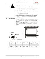
The cable clamp rail is located 185 mm above the ground.
Observe the bending radius!
(With one bend: radius = 10 x diameter)


