


42
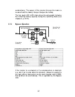
automatically. The supply of the inverter through the mains is
resumed and the battery charger charges the battery.
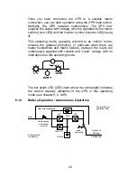
The bar graph LED (LED chain above the pictograph) indicates
the remaining battery capacity during this operating mode (see
chapter 8, p. 48 ff).
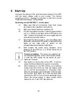
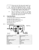
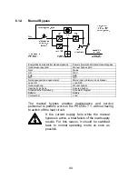
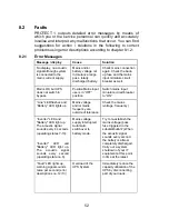
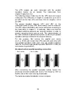
6.1.3 Bypass
Operation
Batterie
Lade GR
GR
WR
Hand-
umgehung
Handumgehungspfad
EUE
Netzeingangs-
sicherungs-
automat
Netz
Schematische
Darstellung
Gesicherte
Schiene:
Verbraucher
Energiefluss bei
gestörtem WR
Energiefluss bei gestörtem WR
Power circuit with faulty INV
Handumgehungspfad
Manual bypass path
Netz Mains
GR REC
EUE SBS
WR INV
Netzeingangssicherungsautomat
Mains input miniature circuit breaker
Lade GR
Load REC
Handumgehung Manual
bypass
Gesicherte Schiene
Secured busbar
Schematische Darstellung
Schematic diagram
Batterie Battery
Verbraucher Load
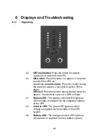
If the inverter is overloaded or if overtemperature is detected,
e.g. also if an inverter defect is detected, voltage is supplied to
the load without interruption via the static bypass switch (SBS)
that switches on automatically. This is signalled by the Bypass
LED.