background image

17

Installation Instructions

Suitable isolation devices include line protecting cutouts, fuses (screw type fus
es are to be removed from the holder), earth leakage trips and contactors.
Connect down draught extractor to an airtight vent hose or vent pipe with a 
120 mm diameter and at least 1 m long.

1

Important: Do not connect down draught extractor to the voltage supply until 
an adequate air outlet has been provided.
Do not connect vent hose or vent pipe to an air shaft, flue or similar which is al
ready in use.
If several Frontline appliances are installed, install down draught extractor be
tween the appliances.
Distance from flammable materials: at least 150 mm

1

Important: Official regulations must be followed when drawing off exhaust air. 

1

Important: Do not conduct exhaust air to a chimney which is used by appliances 
operated with gas or other combustible fuels.

Summary of Contents for FM2500DD-A

Page 1: ...FM2500DD A User manual Down draught extractor ...

Page 2: ...e gral part of our products To ensure optimal and regular performance of your appliance please read this instruction manual carefully It will enable you to navigate all processes perfect ly and most efficiently To refer to this manual any time you need to we recommend you to keep it in a safe place And please pass it to any future owner of the appliance We wish you much joy with your new appliance...

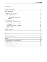
Page 3: ...ppliance 9 Switching the appliance on and off 9 Setting position of down draught extractor 9 Setting fan level 10 Switching intensive fan on and off 10 Using the timer 11 Safety cut out 11 Cleaning and Care 12 Filter 13 What to do if 14 Disposal 15 Installation Instructions 16 Assembly 19 Installing more than one Frontline hob 23 Rating Plate 27 Guarantee Customer Service 28 Service and Spare Part...

Page 4: ...n work on the appliance under supervision General safety The appliance may only be installed and connected by trained registered service engineers Built in appliances may only be used after they have built in to suitable built in units and work surfaces that meet standards In the event of faults with the appliance or damage to the glass ceramic cracks scratches or splits the appliance must be swit...

Page 5: ...ing the appliance must be switched off For safety reasons the cleaning of the appliance with steam jet or high pres sure cleaning equipment is not permitted How to avoid damage to the appliance The glass ceramic can be damaged by objects falling onto it ...

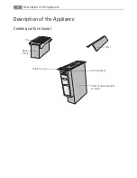
Page 6: ...Description of the Appliance 6 Description of the Appliance Cooking surface layout Upper casing Control panel Frontline strip Shaft of down draught extractor Filter Fin ...

Page 7: ...7 Description of the Appliance Control panel layout Timer indicator Position selection Timer Fan level display Intensive fan On Off Fan level selection ...

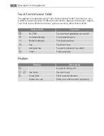
Page 8: ...s from above without covering other sensor fields Displays Sensor field Function On Off To switch the appliance on and off Increase settings To increase position Reduce settings To reduce position Fan To set fan level Intensive fan To switch intensive fan on off Timer Timer selection Display Description no power setting set Á Fan levels Fan level is set e Clean filter Filter must be cleaned Safety...

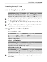
Page 9: ... of down draught extractor Increasing extractor position Reducing extractor position Retaining extractor position 3 If the appliance becomes blocked when changing the position it switches off automatically Control panel Display Pilot light To switch on Touch for 2 seconds lights up To switch off Touch for 1 second none goes out Step Control panel Position of extractor 1 Touch once Middle 2 Touch T...

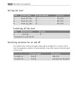
Page 10: ...After that the appliance switches off automatically or switches back to the previously set fan level Step Control panel Fan level display Fan power 1 Touch once 150 m h 2 Touch once À 220 m h 3 Touch once Á 345 m h Step Control panel Display 1 Touch The fan level is switched off Control panel Fan power To switch on Touch 480 m h To switch off Touch previously set fan power ...

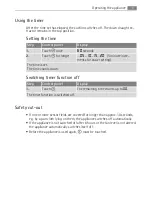
Page 11: ...cloth lying on them the appliance switches off automatically If the appliance is not switched off after 6 hours or the fan level is not altered the appliance automatically switches itself off Before the appliance is used again must be touched Step Control panel Display 1 Touch once 60 seconds 2 Touch for longer 05 10 15 20 5 minute incre ments for easier setting The time is set The time counts dow...

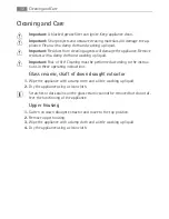
Page 12: ...f fire Cleaning must be performed according to the instruc tions in these operating instructions Glass ceramic shaft of down draught extractor 1 Wipe the appliance with a damp cloth and a little washing up liquid 2 Dry the appliance using a clean cloth 3 Scratches or dark stains on the glass ceramic cannot be removed but do not af fect the functioning of the appliance Upper housing 1 Switch on dow...

Page 13: ... become discoloured but this does not affect the functioning of the filter 7 Install filter springs and upper casing in reverse order 3 The filter must be completely dry before being installed 8 Reset filter sensor by pressing and at the same time for 3 seconds 9 0 goes out 3 If the filter is cleaned before the 30 hours of operation have elapsed it can be reset in the same way 3 If the electricity...

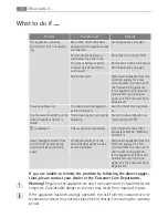
Page 14: ...liquid Remove the cloth or the liquid Switch appliance on again Electronics fault Disconnect appliance from the electrical supply for a few minutes Take the fuse out of the house s wiring system If the appliance still does not operate after switching on again call the Customer Care Department Fuses keep blowing Too many electrical applianc es are connected Switch off electrical applianc es The fan...

Page 15: ...s product may not be treated as household waste Instead it shall be handed over to the applicable collection point for the recycling of electrical and electronic equip ment By ensuring this product is disposed of correctly you will help prevent po tential negative consequences for the environment and human health which could otherwise be caused by inappropriate waste handling of this product For m...

Page 16: ...aught extractor is operated at the same time as a fire place the pressure in the room must be below 4 Pa 4 x 10 5 bar 1 Important If the mains cable is defective it must only be replaced by a qualified electrician or our Customer Care Department in order to prevent hazards 1 WARNING Risk of injury from electrical current The electrical mains terminal is live Make electrical mains terminal free of ...

Page 17: ...ught extractor to the voltage supply until an adequate air outlet has been provided Do not connect vent hose or vent pipe to an air shaft flue or similar which is al ready in use If several Frontline appliances are installed install down draught extractor be tween the appliances Distance from flammable materials at least 150 mm 1 Important Official regulations must be followed when drawing off exh...

Page 18: ...op position 2 Switch off fan level 3 Press in and remove the springs of the fil ter 4 Take filter out 5 Remove upper casing and place on some thing soft 6 Remove the two screws which hold the fin 7 Remove single screw that holds the lever that closes the fin 8 Remove the fin To fit cover 1 Lay cover on the glass ceramic 2 Position cover on the upper housing 3 Mark four holes on the upper casing Us...

Page 19: ...19 Assembly Assembly ...

Page 20: ...Assembly 20 ...

Page 21: ...21 Assembly ...

Page 22: ...Assembly 22 ...

Page 23: ...hs of all appliances to be built in are added together minus 20 mm see also Overview of all appliance widths Example Installing more than one appliance 1 Work out the size of the cut out section and saw it out 2 Remove Frontline strip from the appliances by hand magnetic fastening 3 Lay the appliances one at a time on something soft for example a blanket with the underside facing upwards 4 Screw c...

Page 24: ...nnecting cross bar in the cut out and push up halfway against the appliance 6 Put silicon on the appliance corners that will touch one another Put silicon on the end of the cross bar 7 Loosely screw in fixing plates retaining grips from below on the worktop and on the connecting cross bar ...

Page 25: ...ng grip screws 10 Inject a line of silicon into the gap between the appliances 11 Dampen silicon line with a little soapy water 12 Press rubber block hard against the glass ceramic and draw it slowly along the gap 13 Leave silicon until the next day to harden 14 Carefully remove projecting silicon with a shaving blade 15 Clean glass ceramic thoroughly 16 Replace Frontline strips ...

Page 26: ...king zones Glass ceramic cooking surface with 2 induction cooking zones Gas hob with 2 burners Grill Grill Deep fat fryer Wok 580 mm Glass ceramic cooking surface with 4 radiation cooking zones Gas hob with 4 burners 720 mm Glass ceramic cooking surface with 4 radiation cooking zones Glass ceramic cooking surface with 4 induction cooking zones Gas hob with 4 burners ...

Page 27: ...27 Rating Plate 941 177 540 230 240 V 0 31 kW FDD 180 FM2500DD A 50 Hz AEG ELECTROLUX ...

Page 28: ...s or plastic Costs incurred for calls to put right an appliance which is improperly installed or calls to appliances outside the United Kingdom Appliances found to be in use within a commercial environment plus those which are subject to rental agreements Products of AEG manufacture which are not marketed by AEG European Guarantee This appliance is guaranteed by Electrolux in each of the countries...

Page 29: ...ia 39 0 434 558500 C so Lino Zanussi 26 33080 Porcia PN Latvija 37 17 84 59 34 Kr Barona iela 130 2 LV 1012 Riga Lietuva 370 5 2780609 Verkių 29 LT 09108 Vilnius Luxembourg 35 2 42 43 13 01 Rue de Bitbourg 7 L 1273 Hamm Magyarország 36 1 252 1773 H 1142 Budapest XIV Erzsébet királyné útja 87 Nederland 31 17 24 68 300 Vennootsweg 1 2404 CG Alphen aan den Rijn Norge 47 81 5 30 222 Risløkkvn 2 0508 O...

Page 30: ...30 Sverige 46 0 771 76 76 76 Electrolux Service S t Göransgatan 143 S 105 45 Stockholm Türkiye 90 21 22 93 10 25 Tarlabaþý caddesi no 35 Taksim Istanbul Ðîññèÿ 7 095 937 7837 129090 Ìîñêâà Îëèìïèéñêèé ïðîñïåêò 16 ÁÖ Îëèìïèê p t b ...

Page 31: ...oncise details of the fault 4 The model and serial number of the appliance found on the rating plate 5 The purchase date Please note that a valid purchase receipt or guarantee documentation is required for in guarantee service calls Customer Care For general enquiries concerning your AEG Electrolux appliance or for further informa tion on AEG Electrolux products please contact our Customer Care De...

Page 32: ...www electrolux com www aeg electrolux co uk 374 469 713 B 180107 02 Subject to change without no tice ...

Reviews: