background image

66

NOTE:
THE OPERATIONS INDICATED BELOW MUST 
BE FOLLOWED BY QUALIFIED PERSONNEL 
EXCLUSIVELY, IN CONFORMITY WITH THE 
REGULATIONS IN FORCE.
THE MANUFACTURING FIRM REFUSES ALL 
RESPONSIBILITY FOR DAMAGES TO PEOPLE, 
ANIMALS OR OBJECTS, RESULTING FROM 
THE FAILURE TO COMPLY WITH SUCH 
PROVISIONS.

The appliance is designed to be embedded into 
heat-resistant cabinetry.
Cut a hole in the top of the cabinetry, with the 
dimensions indicated in fig. 3, at a distance of 
at least 50 mm from the appliance border to the 
adjacent walls.

WARNING:

The surrounding cabinetry must resist a minimum 
temperature of 75°C. 
The equipment must not be installed near 
inflammable materials, such as curtains, cloths, 
etc.

( Ref to Fig. 3 on page 8)

MODEL

L (mm)

P (mm)

600-750

560

490

900

820

490

If the are any over-head cabinets above the 
cooktop they must be a minimum of 762 mm (30") 
higher. The distance on the left and on the right 
side from lateral wall should be at least 110 mm 
(4.5”), while the distance from the back wall should 
be at least 25 mm (1”).
It is advisable to isolate the appliance from the 
piece of furniture below with a separator, leaving a 
depression space of at least 10 mm (fig. 4). 
If the hob is going to be installed above an oven, 
precautions must be taken to guarantee installation 
is in accordance with current accident prevention 
standards. Pay particular attention to the position 
of the electric cable and gas pipe: they must not 
touch any hot parts of the oven.

WARNING:

If the hob is going to be installed on the top of a 
built in oven without forced cooling ventilation, 
proper air vents must be installed to guarantee an 
adequate ventilation, with the lower air entering 

with a cross section of at least 200cm

2

, and the 

higher air exiting with a cross section of at least 
60 cm

2

.

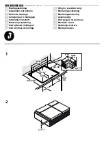
Fastening the top

Every cook-top is equipped with a special washer 
and a set of hooks for mounting the cook-top.
Once the cut-out is made in the cabinet surface, 
the installation procedure is as follows:

Remove the trivets and complete burners from 
the top.
Turn the appliance upside down and lay the ‘S’ 
washer along the external border (fig. 5).
Place the cook-top in the hole made in the piece 
of furniture then block it with the V screws of the 
fastening hooks G (fig. 6 / 6A).

NOTE:

This appliance is not provided with a device for 
exhausting the products of combustion. 
Please check your local regulations to ensure 
installation is in conformity.

Gas Connection

Make sure that the appliance is adjusted for the 
gas type available in your area (see the label under 
the appliance). Follow the instructions indicated in 
the chapter “gas transformations and adjustments” 
for the possible adaptation to different gases. 
The appliance must be connected to the gas 
system by means of still metal pipes or flexible 
steel pipes having continuous walls, in compliance 
with the regulations in force in your area. Some 
models are equipped with cylindrical A and conical 
B connectors for gas supply (fig. 7).

WARNING:

The connection must not stress the gas ramp.

Electric connection

The connection to the electric grid must be carried 
out by qualified personnel and in conformity with 
the regulations in force in your area. 
The voltage of the electric system must correspond 
to the value indicated in the label under the 
appliance. Make sure that the electric system is 
provided with an effective ground connection in 
compliance with the regulations and provisions of 
the law. 
Grounding is compulsory.

D - 

Installation & Warnings

Summary of Contents for CGA 60 WOK

Page 1: ...COD 208196 REV 2 07 06 2006 OPERATION MANUAL Gas Cooktop CGA 60 WOK CGA 75 WOK CGA 90 WOK ...

Page 2: ...f the various functions and operations Experiment with your cooking and take advantage of the features your new appliance offers This manual should be retained for future reference Should ownership of the appliance be transferred please ensure that the manual is also passed onto the new owner A Installation check and warnings Page 3 B Cooking Instructions Page 4 C Cleaning Page 5 D Installation Wa...

Page 3: ...k that it is properly adjusted for the type of gas at disposal Before carrying out the maintenance or cleaning the equipment cut power supply off and make it cool down Make sure that air circulates around the gas equipment Insufficient ventilation produces a lack of oxygen resulting in possible malfunctions In case of an intense or prolonged use of the equipment it may be necessary to improve aera...

Page 4: ...e gas supply can be interrupted by turning the knob clockwise up to the closing position NOTE If there is no power supply it is possible to light the burners with matches setting the knob to the start up point large flame fig 1 BURNERS POWER MJ h POWER Btu h Ø of pots Auxiliary 3 2 3000 10 14 cm Semi rapid 6 3 6000 16 18 cm Rapid 11 6 11000 20 22 cm Wok 17 9 17000 24 26 cm NOTE When the equipment ...

Page 5: ...teel can be stained if it remains in contact with highly calcareous water or aggressive detergents for an extended period of time Stainless Steel can also discolour if in contact with excessive heat Burners and racks These parts can be removed to make cleaning easier The burners must be washed with a sponge and soapy water or with a light detergent wiped well and placed in their housing perfectly ...

Page 6: ...th the lower air entering with a cross section of at least 200cm2 and the higher air exiting with a cross section of at least 60 cm2 Fastening the top Every cook top is equipped with a special washer and a set of hooks for mounting the cook top Once the cut out is made in the cabinet surface the installation procedure is as follows Remove the trivets and complete burners from the top Turn the appl...

Page 7: ...rt the burner Turn the tap up to the minimum position small flame Remove the knob from the tap rod Using a flat tip screwdriver C into the hole F of the tap fig 9 turn the by pass screw up MAINTENANCE Lubricating the taps In the case of tap hardening it is necessary to disassemble the tap and grease it Unscrew the two screws that lock the head flange of the tap Lift the gas adjusting cone and care...

Page 8: ...8 8 1 2 3 4 5 6A 6 8 7 9 10 10 A ...

Page 9: ...31 6 3 6000 NATURAL 10 120 REG 3 AUXILIARY PROPANE 28 55 27 3 2 3000 NATURAL 10 90 REG 4 WOK PROPANE 28 107 60 17 9 17000 NATURAL 10 175 REG The manufacturing firm refuses all responsibility for any possible imprecision in this booklet due to misprints or clerical errors It reserves the right to make all the changes that it will consider necessary in its own products without affecting the essentia...

Page 10: ...MJ h POWER Btu h 1 Rapid burner 11 6 11000 2 Semi rapid burner 6 3 6000 3 Auxiliary burner 3 2 3000 4 Triple ring burner 17 9 17000 8 Control knob for burner E Technical Diagrams CGA 60 WOK CGA 75 WOK CGA 90 WOK ...

Page 11: ...ntify your product for our priority service back up Please attach your invoice to this manual for easy future reference AEG Unit 20 2150 Winston Park Drive Oakville Ontario Canada L6H5V1 Tel 905 829 3980 Fax 905 829 3985 email marketing euro line appliances com For Service Spares EURO PARTS 1 800 678 8352 Important Please record details of your purchase below and mail or fax to AEG cut along line ...

Page 12: ...AEG Unit 20 2150 Winston Park Drive Oakville Ontario Canada L6H5V1 Tel 905 829 3980 Fax 905 829 3985 email marketing euro line appliances com For Service Spares EURO PARTS 1 800 678 8352 ...

Reviews: