

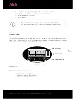

18
PD201808 AEG GRID-TIED THREE-PHASE SOLAR INVERTER (12-30 kW) V.2-18 EN
18
3.2 Before installation
3.2.1 Installation tools
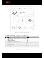
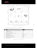
Detailed list of the tools required for installation:
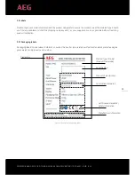
No.
Installation tool
Instruction
1
Marking pen
For marking the installation holes
2
Electrodrill
For drilling in the bracket or wall
3
Hammer
For hammering on the expansion bolts
4
Monkey wrench
For fixing the installation bracket
5
Allen driver
For fastening the screws, removing and installing AC wiring box
6
Straight screwdriver
For AC wiring
7
Megger
For measuring insulation performance and impedance
8
Multimeter
For checking the circuit and AC and DC voltage
9
Electric iron
For welding communications cable
10
Wire crimper
For crimping DC terminals
11
Hydraulic clamp
For crimping ring terminals for AC wiring
Table 7: Required installation tools
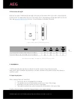
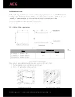
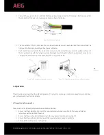
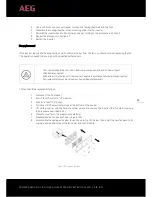
3.2.2 Installation place
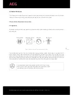
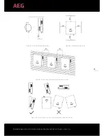
Select the installation place based on the following considerations:
1.
When determining the height of the installation, ensure that the line of sight is at the same level as the
LCD display for reading the inverter parameters smoothly (see figure 8A).
2.
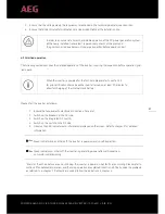
Select a well ventilated place sheltered from direct sun radiation and rain.
3.
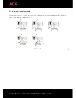
Allow sufficient space around the inverter to enable easy installation and removal from the mounting
surface as well as air circulation. (see figure 8B).
4.
When installing more than one inverter, please ensure that enough space is kept between the individ-
ual inverters. The recommended spacing left and right of the product are shown in figure 8C. The up-
per and lower side of the inverter should have sufficient space to ensure good heat dissipation.
5.
The ambient temperature should range between -25°C ~ 60°C.
6.
The installation position should be such that interference from other electrical devices is avoided.
7.
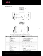
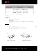
The inverter needs to be installed on a firm and sturdy surface, such as a wall surface, and on metal
brackets. The installation surface should be perpendicular to the horizontal line. Please refer to Figure
8D. Install the inverter vertically or backward ≤1
5°to facilitate heat dissipation. Do not tilt the inverter
forward, horizontally, upside down, forward, backward, nor roll it when you are installing the product.
Do not remove any inverter part or component, otherwise damage to the device and physical injury
may occur.