AEG AS-BBL1-4000 Manual Download Page 6

6

AEG LOW VOLTAGE ENERGY STORAGE UNIT (8 KWH / 12 KWH) INSTALLATION MANUAL

PD202107 V1-21

EN

Ensure you are completely familiar with the 
indications provided the instructions manual 

before attempting installation.

Do not use the battery pack if it is defective, if it 

appears to be cracked, broken or otherwise damaged, 
or if it fails to operate.

Handling or changing components without 
following the instructions in this manual may cause 

personal injury, cause product damage, damage the 
built-in protections of the inverter and ultimately void 
the warranty. 

Do not attempt to open, disassemble, repair, or 

modify the battery pack. The battery pack can only be 
repaired by AEG service personnel.

Use only installation equipment suitable for a solar 
electric installation. 

Only use original parts and components.

To avoid damaging the product and voiding the 
warranty, please ensure that the output voltage of the 
PV array to be connected is lower than the maximum 
rated input voltage of the energy storage system.


 The solar PV modules in the PV array are required 

to comply at least with IEC 61730 class A rating.
When exposed to sunlight, the PV array generates 
dangerous high DC voltages. Installers and operators 
should carefully follow the instructions in this manual 
when handling the storage system and avoid hazardous 
actions that might result in life-threatening situations. 

When exposed to light, solar modules may 

generate dangerous voltages. Cover the modules 
completely with a dark opaque material during 
installation and electrical connection to prevent 
electricity generation. 

 The PV system is by default not grounded. The 

energy storage system must be grounded before 
operation. The system is not suitable for the positive or 
negative grounding systems of solar modules.  Ensure 
the proper grounding of the inverter.

 The electronic components of the energy storage 

system may be damaged by static electricity. Please 
take appropriate protective measures to prevent such 
damages from occurring and voiding the warranty.
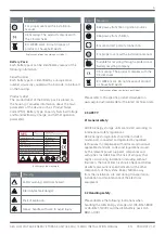
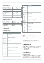
10min

 Do not carry out any installation or 

maintenance when the energy storage system is 
connected to the power supply. To avoid electric shock 
during installation or maintenance, turn off the DC 
switch and AC breaker, and disconnect the DC and AC 
terminals. Wait at least 10 minutes before carrying out 
installation or maintenance.


 During ope

ration, the energy storage system  

or the radiator or its 

components might reach high 

temperatures. Make sure that you do not touch them 
while in operation so to avoid burns. Should you need 
to touch them, allow them to cool down first.

Ensure there is no electromagnetic interference 
from other electrical and electronic equipment at 

the installation site.


Do not install the energy storage system on 

or close to flammable or explosive materials.

Use the battery pack only for the intended purpose in 
combination with the AEG energy storage system. 

Do not insert any foreign objects into any part of the 
battery pack.

2.4


Grid-tied operation safety

Only qualified electricians are allowed to operate the 
energy storage system under the permission of local 
energy authorities. 

All electrical connections must meet the electrical 
standards of the country/region in which the 
installation is located.

Ensure reliable installation and electrical connection 
before operation. 

+ _

Make sure that the battery polarity is connected 

correctly.

 Before opening the storage system cover make 

sure that the storage system is turned off and all the 
external circuits are disconnected. The electrical parts 
and components inside the inverter are electrostatic.

Summary of Contents for AS-BBL1-4000

Page 1: ...E ENERGY STORAGE UNIT 8 KWH 12 KWH INSTALLATION MANUAL PD202107 V1 21 VERSION AEG ENERGY STORAGE INSTALLATION MANUAL AEG LOW VOLTAGE ENERGY STORAGE UNIT SERIES AS BSL1 8000 AS BSL1 12000 AEG BATTERY PACK AS BBL1 4000 ...

Page 2: ...ion Keep this guide in a safe place for further reference as it contains important information for product care maintenance and disposal CONTENTS 1 PRELIMINARY REMARKS 3 1 1 Icons 3 1 2 Product Identification 3 2 Safety 4 2 1 General safety 4 2 4 Grid tied operation safety 6 3 PRODUCT OVERVIEW 8 3 1 General remarks 8 3 1 Product appearance 8 3 1 1 Energy storage system 8 3 2 Battery module 9 3 2 1...

Page 3: ...1 11 16 16 2 Single phase L N PE 230 5000 5000 25 25 50 0 8 0 8 Single phase L N PE 230 5000 5000 25 50 0 8 0 8 Lithium LFP 51 2 42 58 100 Class I IP 20 OVC II PV OVCIII AC Non isolated 10 40 AEG is a registered trademark used under license from AB Electrolux publ Solar Solutions GmbH Brückenstrasse 94 60594 Frankfurt am Main Germany 49 69 800 500 810 info aeg industrialsolar de www aeg industrial...

Page 4: ...afety warning electrical hazard _ Electrolytes leak danger Risk of explosion Kg Heavy handle with care to avoid injury Icon Meaning Keep away from fire or ignition sources Keep away from children _ Ensure correct polarity connection For proper use read the installation manual Suitable for recycling through a professional battery recycling company CE marking The product complies with the CE directi...

Page 5: ... the battery pack _ Handle the battery pack carefully as it may leak corrosive electrolyte To avoid the risk of explosion of the battery pack make sure to observe the following Do not make the battery pack undergo strong impacts Do not crush or puncture the battery pack Do not dispose of the battery pack in a fire To avoid fire risks to the battery pack please make sure to observe the following Do...

Page 6: ... suitable for the positive or negative grounding systems of solar modules Ensure the proper grounding of the inverter The electronic components of the energy storage system may be damaged by static electricity Please take appropriate protective measures to prevent such damages from occurring and voiding the warranty 10min Do not carry out any installation or maintenance when the energy storage sys...

Page 7: ...yte avoid contact with the leaking liquid or gas Electrolyte is corrosive and contact with it may cause skin irritation and chemical burns If you find yourself in any of the below emergency situations resulting from exposure to electrolyte please take the suggested take promptly Inhalation evacuate the contaminated area and immediately seek medical attention Eye contact rinse the eyes with flowing...

Page 8: ...appearance is designed to ensure safety and adaptability to the home environment which are further enhanced by the safe battery access door and by the adjustable feet for greater stability The battery pack AS BBL1 4000 is a LiFePO4 lithium battery unit with BMS battery management system Characterized by high energy density and reliability the battery pack s safety is granted among others by releva...

Page 9: ...t 6 Label 3 2 Battery module 3 1 2 Item Description Size 1 Width 678 mm 2 Depth 205 mm 3 Height 436 mm Weight 60 kg Item Description 1 Product label 2 Handle 3 Warning label 4 Push button of BMS power supply 5 Serial number 6 Battery capacity and warning indicator light 3 2 1 Battery module wiring port The wiring port can be seen in detail after opening the cover plate ...

Page 10: ...ow is the scheme of the CAN communication interface CAN1 is used for BMS parameters monitoring CAN2 is used for inverter communication 1 2 3 4 5 6 7 8 CANH CANL 3 2 3 LED indicators Item Description Remark 1 Push button switch White light 2 100 capacity indicator Green light 3 75 capacity indicator Green light 4 50 capacity indicator Green light 5 25 capacity indicator Green light 6 Warning indica...

Page 11: ...f power from the photovoltaic plant is unavailable the energy to charge the battery and to power the loads will be supplied by the grid Mode 5 A generator can charge the battery bank Mode 6 If the function Time Of Use is on it will ensure that the power to charge the battery and the power sold to the grid can be balanced Mode 7 The UPS Uninterrupted Power Supply Function can ensure that the main l...

Page 12: ...rrent overtemperature undertemperature Peak power 1 5 times of Max continuous power 10S Power factor range 0 8 0 8 Storage Data AS BSL1 8000 AS BSL1 12000 Battery type Lithium LFP Number of battery modules 2 3 Nominal storage capacity kWh 7 68 11 52 Usable storage capacity kWh 6 14 9 22 Battery capacity Ah 150 225 Normal voltage V 51 2 Voltage range V 42 58 Max charge current A 100 Max discharge c...

Page 13: ... of the battery pack Charging cables Network cable 4 3 Wire specifications Energy storage system In order to standardize the specifications of AC and DC connectors or terminals of the compatible inverters please make sure to follow the below requirements for Operating conditions Installation Location Indoor Operating Temperature C 10 45 Operating Temperature Recommended C 15 30 Storage Temperature...

Page 14: ...r and humidity Ensure there are no corrosive gases at the installation site including ammonia and acid vapor Ensure there are no flammable or explosive materials at the installation site or nearby The floor of the installation site must be dry and flat Under no circumstance there should be water on the ground in proximity of the energy storage system Ensure that the ground level is levelled and ca...

Page 15: ...munication wire 1 11 CAN2 communication wire 1 12 Wrench 3 1 13 PV connector 2 14 PV connector removal tool 1 15 RJ45 terminal 2 16 Current sensor 1 17 User manual 1 Battery pack package content The package content of the AEG battery pack includes Item Name Qty 1 Battery pack AS BBL1 4000 1 2 Fuse 1 3 Remote port connector 1 4 Hexagon wrench 1 4 6 Mechanical and electrical installation Step 1 unbo...

Page 16: ...unication wire needs to be added in order to prevent communication interference The above pictures show the position where the RJ45 terminal needs to be added in the AS BSL1 8000 and AS BSL1 12000 systems respectively The RJ45 terminal can be found in the accessories details see below Step 3 Open the door of the system cabinet and open the case of the battery module AS BSL1 8000 AS BSL1 12000 AS B...

Page 17: ...f the battery pack For connection of a single battery pack to the inverter 2 1 3 Item Description 1 Battery pack 2 Breaker 3 Inverter RJ45 terminal Item Description 1 Remote wire 2 Battery wire 3 CAN communication wire Note 1 All CAN1 lines for the internal communication of the battery units are connected in parallel 2 All CAN2 for external communication between the battery unit and the inverter a...

Page 18: ...nect the photovoltaic system to the AEG energy storage system a DC connector specifically designed for connection with storage systems must be used Using other connectors connection devices without explicit authorization from Solar Solutions may result in damage to the AEG energy storage system unstable operation or fire for which Solar Solutions will not take any direct or joint liability Notes R...

Page 19: ... the insulation resistance of the PV panel to the ground should be greater than the safety regulation Ensure that the wires of the cable correspond to the connector terminals and tighten the screws The crimping torque of the screws should be 1 5 2 5 N m Use a multimeter to measure the voltage of the DC input string verify the polarity of the DC input cable and ensure that the voltage of each strin...

Page 20: ...e personal injuries It is not recommended to connect air conditioners and water pumps with the AEG energy storage system AS BSL1 8000 AS BSL1 12000 5 OPERATION 5 1 Operating the AEG battery pack There are two ways to operate the AEG battery pack AS BBL1 4000 CT connection Item Description Remark 1 CT connector Connect to black CT wire 2 CT connectorx Connect to white CT wire 3 CT 4 7 Warnings The ...

Page 21: ...word The default password is 12345 When a sub menu or a function requires the input of a password the following interface will be displayed Method 1 Short PIN2 and PIN3 of Remote port first then press the metal button switch The battery pack will start to work within 25 seconds If there is no communication input after 5 minutes it will stop to function Method 2 Install a switch between PIN1 and PI...

Page 22: ...he below interface In the following section you will find detailed information on each section and sub menu and how to set the parameters of the AEG energy storage system 5 3 2 The main menu The main menu includes 5 sections Status Settings Data Production Information and Battery Capacity Main menu 5 3 3 Checking system information in the Status menu The Status menu displays informations such as P...

Page 23: ... storage system to rely both on the grid and the PV plant to charge the battery select Power source PV system and grid power Power source mode If Power source PV system is selected nothing else needs to be adjusted If Power source PV system grid power is selected the Grid charging settings and the Charging speed settings have to be adjusted In the Grid charging settings you can set the intervals a...

Page 24: ...ad and grid feed in please select Use of energy for house load grid feed in The time intervalls for this have then to be adjusted ĞĞĚͲŝŶ ƟŵĞƐ Setting language and time The sub menu Language Settings allows you to choose the system languages from a set of given languages default English ĂŶŐƵĂŐĞ ƐĞƫŶŐƐ The sub menu Time and date allows you to set a different time and date than the default one Please...

Page 25: ...s related to energy generation from the PV plant grid feed in and environmental statistics Ws ĞŶĞƌŐLJ ŐĞŶĞƌĂƟŽŶ ƐƚĂƟƐƟĐƐ ƌŝĚ ĨĞĞĚͲŝŶ ƐƚĂƟƐƟĐƐ dƌĞĞ ƉůĂŶƟŶŐ ĞƋƵŝǀĂůĞŶƚ CO2 ƐĂǀŝŶŐ ĞƋƵŝǀĂůĞŶƚ 5 3 6 Checking Fault messages If there is any fault during the AEG energy storage system operation a blinking Fault icon will appear in the right upper corner of the LCD screen Clicking on the Fault icon you will ...

Page 26: ...down the storage system will shut down if the battery voltage drops below the given value Low Battery the system will set off an alarm if the battery voltage drops below the given value Restart the storage system will restart after shutdown at the given value ƉĞĐŝĮĐ ĚŝƐĐŚĂƌŐĞ ƐĞƫŶŐƐ Specific Charging settings Generator charging Start voltage the generator will start when the battery voltage is les...

Page 27: ...sion of inverter hardware and software ĚĚŝƟŽŶĂů ƐĞƫŶŐƐ Ͳ ŝŶǀĞƌƚĞƌ ŝŶĨŽƌŵĂƟŽŶ Solar Arc Fault on this option is only available for the US market ĚĚŝƟŽŶĂů ƐĞƫŶŐƐ Ͳ ŽůĂƌ ƌĐ ĂƵůƚ 6 TROUBLESHOOTING 6 1 Battery pack warnings and troubleshooting Check the indicators on the front to determine the state of the battery pack A warning state is triggered when a condition such as with voltage or current or tem...

Page 28: ...20 DC over current fault of the hardware F21 DC leakage flow fault F22 Crash stop if there is a stop button F23 AC leakage current is transient over current F24 DC insulation impedance failure F25 DC reverse irrigation failure F26 The DC bus is unbalanced F27 DC end insulation error F28 Inverter 1 DC high fault F29 AC load switch failure F30 AC main contactor failure F31 AC secondary contactor fai...

Page 29: ...stem 2 Turn off the DC switch and the AC switch Wait one minute then turn on the DC AC switch again 3 If the problem persists please contact your installer distributor Fault code Description Possible solution F23 AC leakage current is transient over current Leakage current fault 1 Check the cable of PV module and inverter 2 Restart the inverter 3 If the problem persists please contact your install...

Page 30: ...uitable for recycling through a professional battery recycling company The wheelie bin symbol on the AEG product labels means that the equipment shall be disposed of as special waste in accordance to the local regulations Fault code Description Possible solution F42 AC line low voltage Grid voltage fault 1 Check if the AC voltage is in the range of standard voltage in specification 2 Check whether...

Page 31: ... in this manual Product installation or operation in extreme environments that are not covered in this manual Product installation or operation in environments not specified in the related international standards Exceeding the operation range of the parameters listed in the product s technical specifications Unauthorized product disassembly and modification or modification of the product s softwar...

Page 32: ...__ __________________________________________________________ __________________________________________________________ __________________________________________________________ __________________________________________________________ __________________________________________________________ __________________________________________________________ ___________________________________________...

Reviews: