UPS IST7 Series (60K-200K)
User Manual
2 Overview
19
UPS1
UPS2
UPSn
……
Bypass unit
Bypass unit
Bypass unit
Figure2-13
RS485 port wiring(Multiple UPSs)
Wiring color in Figure2-12 and Figure2-13 just for display only, it cannot stands for the actual wire color,
for specific color please see the actual wire.
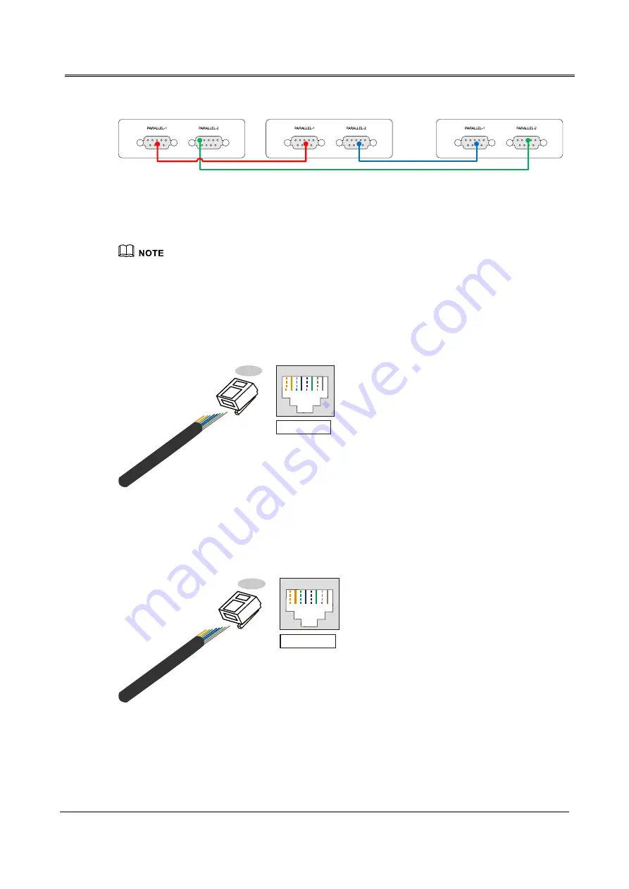
Network port: MODBUS port and RS232 port
1. MODBUS port is used for MODBUS serial port communication, which is to communicate with
upper computer. MODBUS port adopts RJ45 plug. The pin definition as shown in Figure2-14.
1--8
RJ45
plug
RJ45
1 2 3 4 5 6 7 8
1 2 3 4 5 6 7 8
Pin definition
:
Pin 1
:
White orange-MODBUS:A
Pin 2
:
Orange-MODBUS:B
Pin 3
:
White green-Reserved
Pin 4
:
Blue-MODBUS:B
Pin 5
:
White blue-MODBUS:A
Pin 6
:
Green-Reserved
Pin 7
:
White brown-5V power
Pin 8
:
Brown-GND
Figure2-14
Pin definition of MODBUS
2. RS232 port is used for RS232 serial port communication, which is to achieve the external SNMP
card communication. RS232 port adopts RJ45 plug. The pin definition as shown in Figure2-15
1--8
RJ45
plug
RJ45
1 2 3 4 5 6 7 8
1 2 3 4 5 6 7 8
Pin definition
:
Pin 1
:
White orange-RS232:TX
Pin 2
:
Orange-RS232:RX
Pin 3
:
White green-Reserved
Pin 4
:
Blue-RS232:TX
Pin 5
:
White blue-RS232:RX
Pin 6
:
Green-Reserved
Pin 7
:
White brown-5V power
Pin 8
:
Brown-GND
Figure2-15
Pin definition of RS232
Dry contact port
Summary of Contents for IST7 Series
Page 1: ...UPS IST7 60 200kVA Series User Manual www aecups com ...
Page 2: ......


