background image

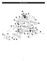
Black Iron Parts List

(3)


Item Part

QTY

Description

41620

1

DE SOS E73 7.5-9.0

1

05818

1

Lift Ram 1.75 x 8”

07772

1

• L.H. Ram with Hose & Fittings

2

05887

1

•• Ram (1-1/2” x 10”)

3

22866

1

•• SAE Mx3/8 90 Degree Elbow

4

22885

1

•• Hose 1/4 x 54”

07783

1

• R.H. Ram with Hose & Fittings

2

05887

1

•• Ram (1-1/2” x 10”)

3

22866

1

•• SAE Mx3/8 90 Degree Elbow

4

22921

1

•• Hose 1/4 x 38”

5

11859

2

• Blue Handle Pin

6

81041

1

• Pivot Bar

7

14185

1

• E-73 Mounting Bracket

8

14704

1

• A-Frame

8a

21541

2

• Chain 5/16 x 38” Gr. 43

8b

8518001026

2

• U-Bolt 7/16-14

8c

20306

4

• Locknut 7/16-14

9a

14596

1

• Lift Unit Cover Front

9b

14288

1

• Lift Unit Cover Rear

10

14290

2

• Lift Unit Cover Bracket

11

16027

1

• Lift Assembly (Unit only)

12

18965

1

• Lift Frame

13

14700

1

• Clevis

14

14439

1

• Lift Arm

15

20027

4

• Bolt H 5/16-18 x 1” Gr. 2

16

20049

4

• Bolt H 3/8-16 x 1” Gr. 2

17

20146

1

• Bolt H 5/8 - 11 x 3-1/4” Gr. 5

18

20102

2

• Bolt H 1/2 - 13 x 3-1/4” Gr. 5

19

20150

4

• Bolt H 5/8 - 11 x 4-1/2” Gr. 5

20

22989

1

• Pin 5/8 x 5-3/4”

21

23050

1

• Pin 5/8 x 4-7/8”

21a

20152

2

• BOLT H 5/8 11 X 5 G5 ZN

22

20305

4

• Locknut 3/8-16

23

20309

12

• Locknut 5/8-11

23a

20140

12

• Bolt H 5/8-11 x 1-3/4” Gr. 5 

24

20307

2

• Locknut 1/2-13

25

22153

1

• Lockbolt 5/16 x 5/8

26

20406

3

• Cotter Pin 3/16 x 1-1/2”

27

20420

2

• Cotter Pin 1/4 x 2”

28

22022

1

• Crank Stand

29

22274

1

• Slotted Nut 1-8

30

22398

1

• King Bolt 1-8 x 5-1/2”

31

22436

2

• Pin 1 x 3”

32

23039

1

• Plow Side Harness

33

22866

1

• SAE Mx3/8 90 Degree Elbow

34

22884

1

• Hose 1/4 x 33”


Item

Part

QTY

Description

41622

1

• Accessory Box

35

23025

1

•• Power Cable

36

07178

2

•• Trip Spring

23067

1

•• Nite Saber LED Kit

09917

1

•• Plow Marker Kit

37

08214

2

••• Plow Marker

38

20027

4

••• Bolt H 5/16-18 x 1 Gr. 2

39

20304

4

••• Locknut 5/16-18

40

20352

8

••• Flatwasher 5/16”

41

11844

1

•• Receiver Tube Cap

42

15372

1

•• Starter Solenoid - 12 volt

43

21832

1

••• Split Bushing

44

23047

1

•• Controller

45

23059

1

•• Truck Side Harness (4 Pin)

41202

1

•• Hardware Bag

46

09124

2

••• Eye Bolt

47

20406

2

••• Cotter Pin 3/16 x 1-1/2”

48

22333

2

••• Pivot Pin 

49

814000005

2

• Spring

50

15187

1

• Breather

Parts indented are included in the assembly under which they are indented.

Summary of Contents for MEYER DIAMOND EDGE

Page 1: ...241 April 2022 Assembly Instructions Standard Operating System with Hands Free Plowing Includes 41680 2022 Printed in the U S A 18513 Euclid Ave Cleveland Ohio 44112 1084 Phone 216 486 1313 www meyerp...

Page 2: ...s disconnect battery prior to installation SAFETY PRECAUTIONS should be used when Quik Lift is in a RAISED position LOWER plow to the ground when vehicle is PARKED OVERHAUL and SERVICE information is...

Page 3: ...2 Black Iron Parts List...

Page 4: ...2989 1 Pin 5 8 x 5 3 4 21 23050 1 Pin 5 8 x 4 7 8 21a 20152 2 BOLT H 5 8 11 X 5 G5 ZN 22 20305 4 Locknut 3 8 16 23 20309 12 Locknut 5 8 11 23a 20140 12 Bolt H 5 8 11 x 1 3 4 Gr 5 24 20307 2 Locknut 1...

Page 5: ...2331 22331 2 Pivot Pin 1 x 3 5 16 60 22375 22375 22375 22375 2 Pivot Pin 1 x 8 3 4 w grease fitting 61 20406 20406 20406 20406 4 Cotter Pin 3 16 x 1 1 2 62 09124 09124 09124 09124 4 Eye Bolt w Locknut...

Page 6: ...r Solenoid B Solenoid Lower A Solenoid Left Angle Motor Solenoid Right Angle Motor Solenoid C Solenoid Motor White A Black B Red C Green Coil Wire Color Code Note Note Ground wire for each coil is Bla...

Page 7: ...es with an alternator relay 5 The WHITE wire will connect to 2015 Later GM vehicles with alternator relay See Meyer Products Service Bulletin SB252 6 The PURPLE wire will connect to the black violet w...

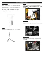
Page 8: ...racket Bottom 7 2 Bolt 1 2 13 x 1 1 12 SS 8 2 Hex Lock Nut 1 2 13 SS 9 4 Flat Washer 1 2 SS 10 2 Neoprene Grommet 1 2 Adjustable Clevis Adjustable Clevis The 14700 adjustable clevis The 14700 adjustab...

Page 9: ...tension is attained when the Trip Spring coils just begin to seperate and then tightening top locknut four additional turns Tighten bottom locknut to secure Eye Boilt in positiion Install Eye Bolt Cap...

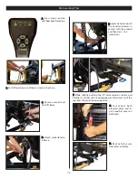
Page 10: ...a frame D D Adjust crankstand until it is no longer in contact with the ground C C Push back on lift frame until both pins springthroughmounton vehicle B B Twist handles on both sides to engage sprin...

Page 11: ...ndles on either side to disengage pins then twist until the leg locks the pin in the open position G G Disconnect both electrical plugs and in stall weather cover on both ends H H Back vehicle away fr...

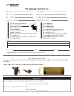
Page 12: ...nker Left Right Operation Plow Light Low High Beam Operation Plow Lights Adjusted Plow Mount Dismount reviewed with Customer Plow Operation reviewed with Customer Warranty Registration Owners Manual R...

Reviews: