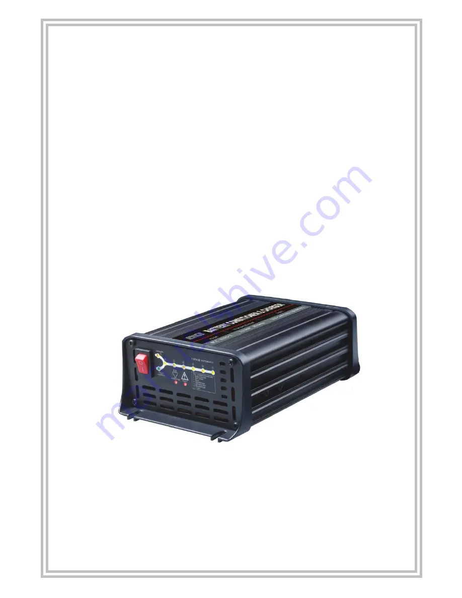
Battery Conditioner and Charger
•
Inverter Technology
MCU Controlled operations
7- Stage Auto Switching Mode
Reverse Polarity Protection
Temperature controlled Cooling Fan
Light weight and Compact
Instruction Manual
Version 7/10
Page 1: ...itioner and Charger Inverter Technology MCU Controlled operations 7 Stage Auto Switching Mode Reverse Polarity Protection Temperature controlled Cooling Fan Light weight and Compact Instruction Manual Version 7 10 ...
Page 2: ...easure 9 2 1 Safety Precautions 9 2 2 Other Precautions 10 3 0 Working with Batteries 11 4 0 The Battery Conditioner and Charger 13 4 1 Function of Individual Components 13 4 2 Protective Features 15 5 0 Charging Batteries 16 Battery out of vehicle connection 16 Battery in vehicle connection 17 Chassis Ground 18 6 0 Installation 20 7 0 Charging Rate 22 8 0 Troubleshooting Guide 23 9 0 Frequently A...
Page 3: ... built in microprocessor chip constantly senses the condition of the battery during operation and controls the whole charging process in providing the right Amperage and Voltage to the battery basing on the designated charging stages The built in automatic 7 stages charging processes Desulphation Soft Start Bulk Charge Absorption Battery Test Recondition and Float makes it the most valuable charge...
Page 4: ...V Absorption Constant Volt until Current drops to 0 75A Constant Volt until Current drops to 1 5 A Battery Test Monitors Voltage for 90 seconds Recondition Constant Current 0 75A up to 16 V for 4 hours Constant Current 1 5A up to 16 V for 4 hours Float Pulsing at 13 8 VDC Efficiency Approximately 85 Safety Short circuit protection Polarity protection Reverse polarity circuit protected Non battery ...
Page 5: ... Absorption Constant Volt until Current drops to 2 25A Constant Volt until Current drops to 3 0 A Battery Test Monitors Voltage for 90 seconds Recondition Constant Current 2 25A up to 16 V for 4 hours Constant Current 3 0A up to 16 V for 4 hours Float Pulsing at 13 8 VDC Efficiency Approximately 85 Safety Short circuit protection Polarity protection Reverse polarity circuit protected Non battery l...
Page 6: ...important for charging severely drained or discharged batteries Stage 3 Bulk Charge Constant Current This charging mode uses constant current at its maximum rate to charge the battery to approximately 80 charge by putting a large amount of power in a short amount of time until the voltage reaches 14 4 volts The charging will continue if the battery terminal voltage has risen above the set limit If...
Page 7: ...iled the test it indicates that during the Absorption stage it was unable to fully charge the battery This reconditioning mode will then begin to introduce a low constant current at high voltage 16V charge for a period of 4 hours before it begins another test Note This mode is used to recover deeply discharged flooded batteries where you could expect a stratified acid high acid content at the bott...
Page 8: ...ithout overcharging or damage the battery This means that the battery can be left connected to the charger indefinitely The battery charger has a 7 step fully automatic charging cycle the cycle is repeated infinitely If the terminal voltage drops below a lower limit the charger automatically goes back to the beginning of the charging curve Various stages of Voltage and Amperage Wave Forms during c...
Page 9: ... and throughout this user s manual are reminders to the operator to exercise extreme care while operating 2 1 Safety Precautions Fuel and battery vapors are highly flammable DO NOT SMOKE NEAR THE VEHICLE DURING CHARGING Never lay tools on vehicle battery You may short the terminals together causing harm to yourself the tools or the battery To protect your eyes from propellant object such as causti...
Page 10: ...nal wiring rules Use the correct input power current Amp fuse rating Do not attempt to charge non rechargeable batteries Never charge a frozen battery If the AC cord is damaged do not attempt to use It must be replaced or repaired by a qualified person Corrosive substances may escape from the battery during charging and damage delicate surfaces Store and charge in a suitable area Ensure all vehicl...
Page 11: ...x with salt water Even small quantities of this combination will produce chlorine gas that can KILL you Whenever possible please follow the manufacturer s instructions for testing jumping installing charging and equalising batteries Never disconnect a battery cable from a vehicle with the engine running because the battery acts like a filter for the electrical system Unfiltered pulsating DC electr...
Page 12: ...ng cables and other steps to minimize the possibility of an explosion or incorrectly charging the battery You should turn the charger OFF before connecting or disconnecting cables to a battery Do not wiggle the cable clamps while the battery is recharging because a spark might occur and this could cause an explosion Good ventilation or a fan is recommended to disperse the gasses created by the rec...
Page 13: ...tage will flash respectively depending on the charging mode it is currently in Fully Charged Its Green LED illuminates Stays ON when the charging has completed Fault Its Red LED will illuminate and flashes when a fault is detected depending on the following conditions 1 Reverse connection between positive and negative of the DC lead 2 Battery charger output shorted Battery Clamps Temperature contr...
Page 14: ...t and stopped after 24 hours The LEDs will illuminate and flash in various patterns to indicate the different stages of charging See below for their indication patterns Indication Stays ON Flashing Extinguish Operation Power ON Charging Fully Charged Fault Red LED Yellow LED Green LED Red LED Power Off Power On Charging 1 Desulphation 2 Soft Start 3 Bulk 4 Absorption 5 Battery Test 6 Recondition 7...
Page 15: ...ith non battery lead it will go into protection state Faulty Battery Alarm Bulk charging has timed out feature built in and it will stop charging after 24 hours This indicates that the battery is faulty and may need to be replaced Over Voltage Protection The charger will automatically goes into protection stage if the voltage is higher than 17 5V Over Temperature Protection If temperature is above...
Page 16: ...ent caps and check the electrolyte level not required on sealed maintenance free batteries The electrolyte should be 6 0 mm 1 4 above the battery s plates If it is low top up with distilled water to the correct level and refit the vent caps STEP 2 1 BATTERY OUT OF THE VEHICLE CONNECTION Connect the RED lead battery clip from the charger to the Positive battery post Connect the BLACK lead battery c...
Page 17: ... to the vehicle s chassis Connect the RED lead battery clip from the charger to the Positive battery terminal For Negatively Earthed Vehicle Most common Connect the BLACK lead battery clip from the charger to the vehicle s chassis Keep away from the fuel line or moving parts Figure 3 Connect the BLACK lead battery clip from the charger to the Negative battery terminal For Positively Vehicle Earthe...
Page 18: ...where the battery charger is installed In a vehicle connect the chassis ground lug to the chassis of the vehicle In a boat connect to the boat s grounding systems In a fixed location usually indoor connect it to the building earth Rear view of the Charger Figure 5 STEP 3 CONNECT TO 110V 220 240VAC MAINS POWER Connect the battery charger to the 110V 220 240V AC mains powered socket and turn ON the ...
Page 19: ...t had decided the yellow LED at the stage where it starts will flash indicating the current process The charging process will continue after completing one stage and move to the other stage automatically indicated by the flashing yellow LED until it has fully charged the battery indicated by the Fully Charged Green LED lights up If there is a fault detected the Red Fault LED will flash indicating ...
Page 20: ...nnot come in contact with the rain use Ensure that both charger and battery are in a well ventilated space during charging The charger end plates include mounting flanges which are designed for easy mounting If there is a need to permanently fix the charger it should be mounted on a suitable horizontal or vertical panel with at least 10cm clearance from the end plates to the wall to provide adequa...
Page 21: ...110V 220V 240V AC Supply Figure 7 You will need 2 pieces ring terminals cable lugs an inline fuse holder and a fuse with a rating equal to or more than twice of the chargers output See below 5A Charger use 10 Amp fuse 10A Charger use 20 Amp fuse 15A Charger use 30 Amp fuse 20A Charger use 40 Amp fuse Connection Refer Figure 7 1 Cut off the supplied battery clips and ensured that you leave sufficie...
Page 22: ...d fuse 8 When everything is in order plug the charger to the main 110V 220V 240V power supply and switch ON to start the charging operation If the charger is used in a Permanent Hard Wired application it is best to leave the charger connected to mains power turned On so that it can maintain the battery fully charged Ensure any modification to the 110V 220 240V AC mains lead is carried out by a qua...
Page 23: ...each other OR Check the clips are correctly connected to the battery Non Battery Link _ _ Non battery link Please choose the right battery type for connection Faulty Battery Bulk LED _ Bulk charging has timed out and stopped after 24 hours Battery is faulty and may need to be replaced Over Voltage _ _ The 12V battery voltage is above 17 5V Disconnect the charger and check the battery voltage This ...
Page 24: ... power is used for a long time for example a map reading light is left on for a week or more This Battery Conditioner and Charger is designed to charge from as little as 2 0 Volts If the voltage is lower than 2 0 Volts use a pair of booster cables to connect between two batteries to provide more than 2 0 Volts to the battery being charged The charger can then start to charge the battery and the bo...
Page 25: ...latest information available at the time of printing The right is reserved to make any changes at any time without obligation to notify any person or organization of such revisions or changes Furthermore the manufacturer or its sales agents are not liable for errors contained herein or for incidental or consequential damages including lost profits in connection with the furnishing performance or u...
Page 26: ...riginal warranty or three months 3 months from the date of repair whichever is longer 3 This warranty only extends to the first owner and not assignable or transferable to any subsequent owner 4 Cost of delivery charges incurred for the repair of the product to and from the manufacturer will be borne by the owner 5 This limited warranty covers only those defects that arises as a result of normal u...
Page 27: ...rranty of merchantability or fitness for use shall be limited to the duration of the foregoing limited warranty Otherwise the foregoing limited warranty is the owner s sole and exclusive remedy and is in lieu of all other warranties whether express or implied The manufacturer or any of its exclusive sales agents shall not be liable for any consequential or incidental damages or losses arising of t...