96-8006123_11-03-2021
Information subject to change
27
8302 OPERATOR’S MANUAL – SECTION 6
2.
Make sure the back panel breaker switch on
both amplifiers is in the ON position.
3.
Press the Power switch on both the Master and
the Follower amplifier to energize the amplifi
-
ers. Energizing the Master amplifier first is rec
-
ommended, although not absolutely required.
4.
Wait for the green RUN LEDs to illuminate on
both amplifiers.
5.
Adjust the input signal level to achieve the
desired output level.
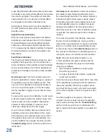
6.4.5 Multiamp System Operation
In multiamp systems, the Master amplifier controls
several operating functions for both amplifiers in
the system, so the Follower amplifier is said to be
“interlocked” with the Master amplifier. The func
-
tions controlled by the Master amplifer include
input signal, operating status, mode of operation
(controlled-voltage or controlled-current operation)
and amplifier compensation.
Because the amplifiers in a multiamp system are
interlocked, the main and fault status indicators of
both amplifiers in the system must be considered
to determine the current status and the necessary
remedies to return the system to operational status
when a fault condition occurs.
Run/Standby Indicators
When each amplifier in a multi-amp system is
energized, the amplifier will be placed in Standby
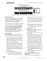
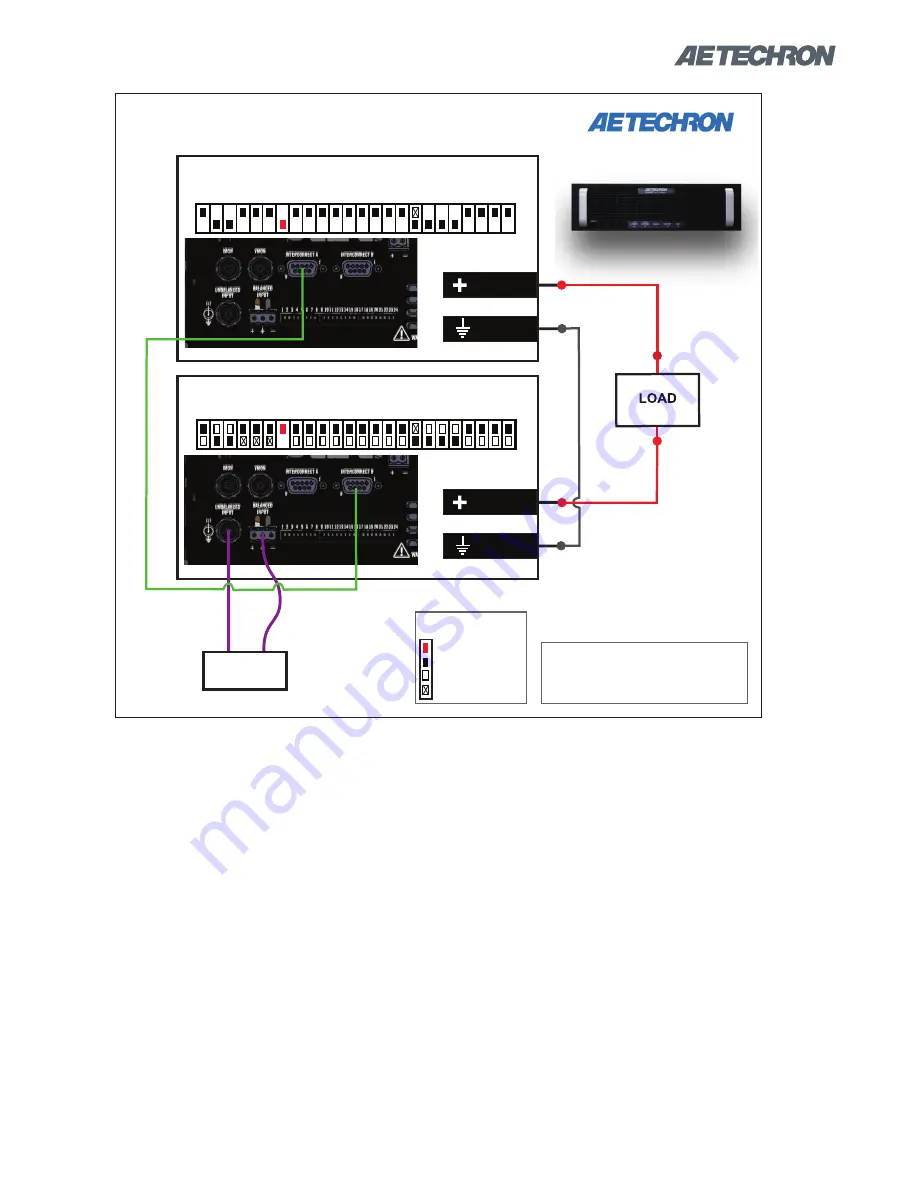
Figure 6.13 – 8302 Push/Pull system setup
PUSH/PULL
DB9 CABLE
8302 AMP #1 -
MASTER
and/or
Signal
Generator
SYSTEM REQUIREMENTS:
(2) 8302 amplifiers
(1) 8302 Multi-amp Kit (69-8005462)
8302 AMP #2 -
FOLLOWER
AMPLIFIER
OUTPUTS
NOTE: No ground
should be used on
either side of the
load with this
configuration.
OUTPUT
GND
AMPLIFIER
OUTPUTS
OUTPUT
GND
8302 PUSH/PULL SYSTEM
8302
AMPLIFIERS
KEY FOR DIP SWITCH
SETTINGS:
REQUIRED
DEFAULT
OPTIONAL
NOT RECOMMENDED
1 2 3 4 5 6 7 8 9 10 11 12 13 14 15 16 17 18 19 20 21 22 23 24
1 2 3 4 5 6 7 8 9 10 11 12 13 14 15 16 17 18 19 20 21 22 23 24
Summary of Contents for 8302
Page 2: ......

