Adveco AGUADENS 210T Instructions For Installation, Use And Maintenance Manual Download Page 68

68

60T - 280T

COSMOGAS

16 - START-UP

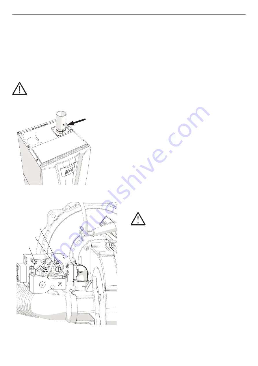
Figure 16-9 - Taking combustion analysis

Figure 16-10 – Gas valve

D - Gas inlet tapping point.

E - CO2 regulation screw.

F - Factory regulation screw (do not touch).

E

D

F

E

D

F

020010.01.022

16.8 - Controlling the level of 

CO2 and any adjustments

Table  16-8  shows  the  correct  values  of  CO2  for  a  boiler 

working in normal conditions, at an altitude of less than 1000 

metres. A  different  value  from  the  one  shown  can  cause 

malfunctions. A combustion analysis must be carried out to 

check  and  make  any  necessary  adjustment  to  this  value. 

Proceed as follows:

16.8.1 - Check the CO2 content and make 

any necessary adjustment on boiler 

models 70T

WARNING! If during this procedure a CO value 

of more than 1000 ppm is detected, turn off the boiler 

and contact the dealer.

1.- If one is not already present, you will have to make a hole 

for the combustion analysis, located about 200 mm from the 

exhaust gases outlet pipe (see figure 16-9 corresponding to 

stopper “F”).

2.- Turn on the boiler and open the link between terminals “10” 

and “11”;

3.- Make sure that the temperature demanded is higher than 

that of the boiler/hot water heater;

4.-  Go  into  the  installer  menu  (see  section  17.15)  and  set 

parameter 

2010

 to 

HIGH.

 Now the boiler will operate 

at maximum power for 20 minutes;

5.- Wait two or three minutes for the CO2 to stabilise;

6.- Insert the sensor to read the value of CO2 in point “F” shown 

in figure 16-9;

7.- Compare the value of CO2 detected with that shown in table 

16-8; make sure you read the value for the type of gas being 

used. If the value of CO2 is not that shown in table 16-8, you 

must correct it using screw “E” in figure 16-10. Using a 2.5 

mm six-sided spanner (turn the screw clockwise to reduce 

the value of CO2 and anticlockwise to increase it), make 

small turns, always waiting for the CO2 value to stabilise 

before continuing with further movements, until you reach 

the desired value.

8.- Once you have reached the correct value of CO2 as in table 

16-8, seal the screw with red paint or a similar system to 

discourage any tampering with it.

9.- Set parameter 

2010

 at 

LO

. The boiler will now operate 

at minimum power for 20 minutes.

10.- Wait two or three minutes for the CO2 to stabilise;

11.- Compare the reading for the value of CO2 with that shown 

in table 16-8, make sure you read the value for the type of 

gas being used. The value of CO2 must fall within the values 

shown, if that is not the case you must turn off the boiler and 

contact the manufacturer.

12.-  Set  parameter 

2010

  to 

OFF

  to  return  the  boiler  to 

normal operation.

13.- Close the combustion analysis hole in figure 16-9, with 

a  suitable  stopper  “F”  as  shown  in  the  manufacturer’s 

instructions for the outlet pipe.

WARNING! Once stopper “F” is in position with 

the boiler at maximum power, check there are no leaks 

of exhaust gases.

F - Taking combustion analysis

F

020010.01.042

Summary of Contents for AGUADENS 210T

Page 1: ...62403578 R02 01 06 2019_UK ADVECO INSTALLATION USE AND MAINTENANCE MANUAL 70T 140T 210T 280T GAS CONDENSING FREE STANDING BOILER MYDENS GAS CONDENSING FREE STANDING HOT WATER HEATER AGUADENS...

Page 2: ...se only by a qualified heating installer Refer to the User s Information section for your reference Maintenance at least once a year the user must call a Competent Person for routine maintenance If yo...

Page 3: ...ly by the user for possible future consultation If the appliance must be transferred or if you should move and leave the unit to another user always ensure that this manual remains with the new user a...

Page 4: ...ns and minimum distances to be observed 27 8 INSTALLATION Dimensions and centre space distances MYDENS boiler 28 9 INSTALLATION Dimensions and centre space distances AGUADENS hot water heater 30 10 IN...

Page 5: ...nversion of boiler models 70T from one type of gas to another 63 16 5 Conversion of boiler models 140T to 280T from one type of gas to another 65 16 6 Ignition 67 16 6 1 MYDENS boiler ignition 67 16 6...

Page 6: ...er 86 18 7 Maintenance and cleaning of condensate outlet system 86 18 8 Connection of Display to other burners 87 18 9 How to move a control board 88 18 10 Emptying the boiler 90 18 11 Minimum and max...

Page 7: ...nd 3rd family gases BS 6891 2005 A2 2008 Installation of low pressure gas pipework of up to 35 mm R1 1 4 in domestic premises 2nd family gas specification BS 5482 1 2005 Code of practice for domestic...

Page 8: ...ld c Appliance with carbon steel manifold cv Appliance with 2 way valves and carbon steel manifold 70T Free standing boiler with maximum heat input of 69 9 kW 140T Free standing boiler with maximum he...

Page 9: ...undergo suitable operations for it to be reused or treated to remove and safely dispose of any substances that are dangerous for the environment This will enable all the raw materials to be recycled T...

Page 10: ...Hot water outlet pipe 8 9 Heat exchanger 10 11 12 Stopper not present 13 Water pressure sensor present in burner 1 MASTER 14 Sparks generator 15 Ignition cables 16 Water flow rate gauge 17 2 way motor...

Page 11: ...25 Fan 26 Water inlet temperature sensor 27 LH ignition electrode 28 RH ignition electrode 29 30 31 Flue gases check valve 32 Check valve magnet 33 Check valve sensor 3 MAIN COMPONENTS Figure 3 2 Int...

Page 12: ...Board 885 IF on request 14 Electrical connections 15 16 17 Control panel 18 19 Top front casing 20 Burner 1 command and control board 21 Bottom front casing 24 Pressure switch against outlet blockage...

Page 13: ...connector 29 Exhaust gases temperature sensor blue connector 1006 30 Exhaust gases outlet manifold 31 Water inlet pipe 32 33 Condensate level sensor 34 39 Primary heat exchanger temperature fuse 3 MA...

Page 14: ...on request 14 Electrical connections 15 16 17 Control panel 18 Burner 2 command and control board 19 Top front casing 20 Burner 1 command and control board 21 Bottom front casing 24 Pressure switch ag...

Page 15: ...9 Exhaust gases temperature sensor blue connector 1006 30 Exhaust gases outlet manifold 31 Water inlet pipe 32 33 Condensate level sensor 34 39 Primary heat exchanger temperature fuse 3 MAIN COMPONENT...

Page 16: ...nlet pipe 7 Hot water outlet pipe 8 Burner 2 3 4 SLAVE 9 Air intake 10 Passage of electrical wires 11 Air intake filter 12 Exhaust gases outlet 13 Board 885 IF on request 14 Electrical connections 15...

Page 17: ...010 BURNER 2 Not present in models 180T and 210T BURNER 1 Master BURNER 3 BURNER 4 22 Top cover 23 General ON OFF switch 27 Fan cover 28 Exhaust gases temperature safety fuse red connector 29 Exhaust...

Page 18: ...Pre mixed burner 13 Ignition electrodes 14 Sparks generator 15 Water inlet temperature sensor 16 Fan 17 Back flue preventer valve 20 Gas valve 22 Detection electrode 24 VRC heat exchanger 25 Water ou...

Page 19: ...re safety fuse 12 Pre mixed burner 13 Ignition electrodes 14 Sparks generator 15 Water inlet temperature sensor 16 Fan 17 Back flue preventer valve 20 Gas valve 22 Detection electrode 24 VRC heat exch...

Page 20: ...ixed burner 13 Ignition electrodes 14 Sparks generator 15 Water inlet temperature sensor 16 Fan 17 Back flue preventer valve 20 Gas valve 22 Detection electrode 23 Inlet and outlet manifold 24 VRC hea...

Page 21: ...ixed burner 13 Ignition electrodes 14 Sparks generator 15 Water inlet temperature sensor 16 Fan 17 Back flue preventer valve 20 Gas valve 22 Detection electrode 23 Inlet and outlet manifold 24 VRC hea...

Page 22: ...that is compatible with the characteristics of the boiler itself Figure 4 5 Modulation of model 280T boiler 4 1 2 AGUADENS hot water heater operation and intended use The AGUADENS product is a conden...

Page 23: ...in figure 10 2 and detail 36 in figure 11 1 is not supplied to give the installer the option of being able to connect any pump even a modulating one When choosing this pump the designer must check th...

Page 24: ...led in rooms with a thin floor a resonating noise could be generated The installation of noise reduction elements is required WARNING Do not let too much dust accumulate on the boiler WARNING The boil...

Page 25: ...ans dryers compressors air heating units etc that might take air away from the boiler WARNING Extractors or similar devices for the removal of air from the heating unit might reduce the ventilation re...

Page 26: ...fixed to the pallet for transportation Be careful when opening it take the cardboard box off by lifting it upwards after detaching it from the pallet 6 1 3 Lifting the boiler For convenience during in...

Page 27: ...maintenance it is necessary to leave free spaces around the boiler as shown in figures 7 1 and 7 2 The dimensions and connection centre space distances for the boilers are shown in figures 8 1 8 2 9...

Page 28: ...space distances MYDENS boiler Figure 8 1 Dimensions and centre space distances of attachments for models 70T and 140T References in figure 8 3 Figure 8 2 Dimensions and centre space distances of atta...

Page 29: ...UTLET 70T 1 1 2 1 1 2 136 mm 110 mm 1 28 mm 140T 1 1 2 1 1 2 136 mm 110 mm 1 28 mm 180T DN65 PN16 DN65 PN16 136 mm 160 mm 1 1 4 28 mm 280T DN65 PN16 DN65 PN16 136 mm 160 mm 1 1 4 28 mm Connections and...

Page 30: ...distances AGUADENS hot water heater Figure 9 1 Dimensions and centre space distances of attachments for models 70T and 140T References in figure 9 3 Figure 9 2 Dimensions and centre space distances o...

Page 31: ...m do not obstruct and do not add any connection Figure 9 3 Table of diameters of connections in figures 9 1 and 9 2 C B E A D A 020013 01 013 Figure 9 4 Assembly of flanges and reductions on threaded...

Page 32: ...safety valve against too high pressure so that the installer is able to choose the valve that suits the system s operating pressure check the operating pressure of the boiler in the technical data sec...

Page 33: ...mple of connection diagram of MYDENS with hydraulic separator and storage tank 24 Return from the central heating system 25 Stopper for dirt outlet 26 Central heating system mixer valve 27 System outl...

Page 34: ...1 Nipple 2 Gasket 3 Manifold 4 Catch basin for sensor Valve 11 5 INAIL thermometer 6 INAIL pressure gauge 7 INAIL safety valve 8 Connection group 11 INAIL fuel isolation valve 12 Inspection basin 13...

Page 35: ...rials metallic chips shavings grease deposits and dirt in general Residues from welding can also cause corrosion both in new systems and after modifications and repairs In old systems planned to work...

Page 36: ...different metals or by the presence of chlorides c DEPOSITS These are insoluble organic and inorganic substances DIRT RESIDUES FROM WORK 10 8 MYDENS boiler heat circuit outlet In order to avoid consta...

Page 37: ...ve a circulation pump For the size of the pumps to be used the designer must consider the system s hydraulic resistances and the hydraulic resistances of the boiler itself For this purpose the hydraul...

Page 38: ...hat the installer is able to choose the valve that suits the system s operating pressure check the operating pressure of the boiler in the technical data section The installation must be carried out i...

Page 39: ...L safety pressure switch 15 INAIL safety pressure switch 16 Expansion tank connection joint WARNING The sensor of valve 11 figure 11 2 is positioned in the basin for sensor 4 and closed with the relat...

Page 40: ...of power installed A domestic hot water circulation pump must be installed to fill the storage tank The hydraulic resistance of the hot water heater is shown in the form of a graph in figure 11 4 For...

Page 41: ...e domestic hot water circuit must be made with materials resistant to temperatures of at least 95 C and a pressure of 10 bar Otherwise e g with plastic piping the system must be fitted with the releva...

Page 42: ...back into the room In particular the condensate outlet system must be performed with a pipe with an internal diameter equal to or greater than 13 mm be installed in such a way as to prevent the liquid...

Page 43: ...the appliance with a contact opening distance of at least 3 mm as envisioned by the current sector regulations Respect the polarity between the neutral and phase wires when connecting the appliance Ma...

Page 44: ...the external sensor has been enabled the icon shows on the display Proceed with the steps given in section 17 9 1 to set the correct adjustment values for the supply temperature according to the outdo...

Page 45: ...ure 10 2 or similar Proceed as follows for the electrical connections refer to figures 13 4 and 13 5 1 Disconnect the electric power supply from the boiler 2 Lay a two pole electric cable with a minim...

Page 46: ...mm which goes from the hot water heater to the storage tank temperature sensor and connect it to the hot water heater on terminals 8 and 9 Manifold temperature sensor 5 Connect the other end of the c...

Page 47: ...AS 13 INSTALLATION Electrical connections Figure 13 5 MYDENS boiler electrical connections Example of system shown in figure 10 2 Figure 13 4 MYDENS boiler electrical connections Example of system sho...

Page 48: ...48 60T 280T COSMOGAS 13 INSTALLATION Electrical connections Figure 13 6 AGUADENS hot water heater electrical connections Example of system shown in figure 11 1...

Page 49: ...ollow the 885 HC command manual for the instructions on how to cascade appliances 885 HC Cascade sequencer MASTER appliance 1 SLAVE appliance 2 SLAVE appliance 3 SLAVE appliance 4 to 8 Heating unit pu...

Page 50: ...the room in which it is located Therefore all precautions must be taken regarding ventilation of the rooms as prescribed by the national and or local regulations During operation especially in winter...

Page 51: ...nce If more than one boiler is installed each boiler should be provided with its own condensate outlet The flue gas exhaust air intake system can be extended up to a maximum distance as indicated in s...

Page 52: ...g the rods to the framework of the external cover figure 15 15 8 Attach the cover AB using screws C to the framework of the external cover as shown in figure 15 16 9 Put on the covers AA and AC in the...

Page 53: ...002 H J A 62610111 005 K K 62610111 006 J K 62610111 007 G 62610111 009 Figure 15 1 Figure 15 2 Figure 15 3 Figure 15 4 Figure 15 5 Figure 15 6 Figure 15 7 Figure 15 8 Figure 15 9 Figure 15 10 Figure...

Page 54: ...10 006 AB C 62610110 004 C Y AC X AA 62610110 005 R B R S B B 62610110 007 C C AD AD 62610110 008 E A 62610111 012 Q B 62610111 013 62610111 023 Figure 15 12 Figure 15 14 Figure 15 16 Figure 15 17 Fig...

Page 55: ...5 23 M W L O N 110 mm 80 mm W P 62610111 044 D D D 62610111 030 Figure 15 26 Figure 15 27 G AE 62610111 021 Figure 15 25 Figure 15 24 B B 62610112 006 Figure 15 28 Z 62610111 032 B AS AR AR J AS 62610...

Page 56: ...AC and AD in figure 15 54 respectively in front of figure 15 51 and behind figure 15 52 the previously assembled metal sheets in the direction shown by the arrows Then put in screws B as in figure 15...

Page 57: ...610111 002 H J A 62610111 005 K K 62610111 006 J K 62610111 007 G 62610111 009 Figure 15 32 Figure 15 33 Figure 15 34 Figure 15 35 Figure 15 36 Figure 15 37 Figure 15 39 Figure 15 40 Figure 15 41 Figu...

Page 58: ...018 B 62610111 019 Figure 15 48 Figure 15 49 Figure 15 50 Figure 15 51 Figure 15 52 Figure 15 53 V 62610111 040 Figure 15 47 E A 62610111 012 Q B 62610111 013 62610111 023 Figure 15 43 Figure 15 45 F...

Page 59: ...62610111 024 C C AF AG R B 62610111 025 AH 62610111 026 B C S R B 62610111 027 Figure 15 57 Figure 15 58 Figure 15 59 Figure 15 60 Figure 15 62 S 62610112 011 Figure 15 61 C AL AM C AM AL 62610111 028...

Page 60: ...r Z 62610111 032 Figure 15 67 Figure 15 69 M W L O N 160 mm 110 mm W P 62610111 029 D D D 62610111 030 AP Z AN Z 62610111 031 Figure 15 68 Figure 15 70 B AS AR AR J AS 62610112 009 AN 62610112 007 B 6...

Page 61: ...be filled again as explained above WARNING Once the boiler is back on check that no exhaust gases are escaping from stopper A 16 1 3 Filling the central heating system If the message Err 59 appears on...

Page 62: ...eding 50 mbar If the gas system must be inspected at pressures over 50 mbar turn the cock located immediately before the boiler to isolate it from the system In figures 8 1 8 2 9 1 and 9 2 you can che...

Page 63: ...int gasket H in figure 16 2 9 Replace fork A in the locking housing 10 Tighten joint H in figure 16 2 11 Open the gas supply valve 12 Check that there are no leaks from joint H in figure 16 2 WARNING...

Page 64: ...A Connector from burner 1 MASTER B Connector from display C Connector from burner 2 D Connector from burner 3 E Connector from burner 4 Figure 16 5 Burners position Burner 2 Burner 1 Master Burner 3...

Page 65: ...if present as shown below 4 Carry out the conversion in Burner 3 following points 1 to 16 of section 16 4 After converting Burner 3 continue with Burner 4 if present as shown below 5 Carry out the con...

Page 66: ...from 8 4 to 9 0 CO2 Methane gas G20 at minimum power from 8 4 to 8 6 O2 Methane gas G20 at maximum power from 5 2 to 5 6 O2 Methane gas G20 at minimum power from 5 7 to 5 9 CO2 Methane gas G25 at max...

Page 67: ...ssure must match that shown in the table in section 19 Proceed as follows to verify the pressure 1 Close the gas cock 2 access the boiler s internal parts by following the procedure described in secti...

Page 68: ...stabilise 6 Insert the sensor to read the value of CO2 in point F shown in figure 16 9 7 Compare the value of CO2 detected with that shown in table 16 8 make sure you read the value for the type of ga...

Page 69: ...ensor from the corresponding burner and inserting the analyser sensor into the hole 12 Set parameter 2201 to OFF 13 Work on the remaining burners repeating the steps from point 3 to point 11 bearing i...

Page 70: ...through and changing the value of the parameters T On off switch 17 1 Water pressure check 17 1 1 MYDENS boiler checking water pressure If the pressure inside the central heating circuit falls below 0...

Page 71: ...perate for the service required To turn off the boiler do the following 1 Use switch T in figure 17 1 to remove electrical voltage 2 turn off the gas cock 17 5 AGUADENS hot water heater adjusting the...

Page 72: ...wer the temperature calculated and match the desired room temperature 17 9 2 Climate control switching the central heating service on and off The climate control service is completely automatic includ...

Page 73: ...mperature corresponding to projected outdoor temperature winter Par 2023 Outdoor spring temperature Par 2024 delivery temperature corresponding to projected outdoor spring temperature Par 3016 Minimum...

Page 74: ...1055 Burner 1 Number of failed ignitions of burner n 1056 Burner 1 Number of hours worked h x 10 1057 Burner 1 Number of hours worked on domestic hot water with puffer tank h x 10 1059 Time interval...

Page 75: ...18 8 WARNING Any variations made to the parameters must be noted in the Customised values column in the following table in order to facilitate any future replacements of the command and control board...

Page 76: ...Multi burner delta temp burner ignition C from 0 to 20 5 5 2106 Multi burner delta temp burner switch off C from 0 to 20 5 5 2107 Multi burner maximum increase in temp compared to that calculated C fr...

Page 77: ...od order of the electrical connections between gas valve and control board A If the electrical connections are interrupted reset them B If the connections are in good order try to replace the gas valv...

Page 78: ...ternal safety devices A Check the connection to the external safety device B Check intervention of exhaust gases differential pressure switch C Check for any possible blockage of flue gas outlet A Che...

Page 79: ...aust gases high temperature error A Check the combustion efficiency of the burner the error is flagged up against efficiency must be above that required by regulations B Check that the exhaust gases t...

Page 80: ...ers 3000 section 20 Err 107 Software error inside control board Replace the command and control board Err 108 Software error inside control board Replace the command and control board Err 109 Error at...

Page 81: ...whether the air intake and flue gas outlet ducts have any blockages signs of corrosion physical damage water marks or signs of rust 2 Make sure the externally assembled intake grids and flue exhaust o...

Page 82: ...spark plugs 4 dismantle air manifold A in Figure 18 3 by turning it clockwise and then taking it out leftwards 5 undo junction H in figure 18 4 paying attention to the gasket in the joint 6 with the h...

Page 83: ...ARNING DO NOT use a metal brush Only use a brush with bristles made of nylon or a similar material 5 using an extractor suck up the unburnt residue found inside the combustion chamber H 6 with the sam...

Page 84: ...R H B A C T S R H B A C T S 020009 01 031 020009 01 032 WARNING The gasket ensures the combustion chamber is sealed If the gasket is damaged DO NOT reuse it it must be replaced along with the burner u...

Page 85: ...to use sliding callipers to respect the tolerances given in Figure 18 7 A Left hand ignition electrode B Right hand ignition electrode C Detection electrode R H N C A E Q B F S L G M D 020022 01 009...

Page 86: ...onths or year depending on how they are controlled by the local regulations in force The neutralising contents of the box must be replaced when the level of pH falls below the level required by the re...

Page 87: ...D Connector for dialogue Burner 3 Only in models 210T and 280T E Connector for dialogue Burner 4 Only in model 280T 1 Disconnect the electric power supply from the boiler 2 Follow the steps of sectio...

Page 88: ...from Burner 1 Master 4 Disconnect all the other connectors from Burner 1 Master s control board 5 Remove the control board of Burner 1 Master from the boiler 6 Follow points 3 to 5 to remove the cont...

Page 89: ...89 60T 280T COSMOGAS 18 MAINTENANCE Figure 18 12 Setting parameters 3001 3050 and selectors S4 Models 280T Models 210T Models 140T Models 70T...

Page 90: ...ort this temperature 2 access parameter 2010 2200 for multi burner models located in the installer menu see section 17 15 3 set the parameter at the following value a Lo to force the burner or all the...

Page 91: ...must correspond to figure 18 13 The temperature sensors are 1001 1002 1006 and 1007 Figure 18 13 Water sensors curve Figure 18 14 Outdoor temperature sensor curve 18 MAINTENANCE 18 15 Outdoor tempera...

Page 92: ...92 60T 280T COSMOGAS 18 16 Multi wire wiring diagram for models 70T Figure 18 15 Multi wire wiring diagram part 1 continues on next page 18 MAINTENANCE...

Page 93: ...93 60T 280T COSMOGAS 18 MAINTENANCE Figure 18 15 Multi wire wiring diagram part 2 continued from previous page...

Page 94: ...94 60T 280T COSMOGAS 18 MAINTENANCE Figure 18 16 Multi wire wiring diagram part 1 continues on next page 18 17 Multi wire wiring diagram for models 140T 210T and 280T...

Page 95: ...95 60T 280T COSMOGAS 18 MAINTENANCE Continues Figure 18 16 Multi wire wiring diagram part 2 continues on next page...

Page 96: ...96 60T 280T COSMOGAS 18 MAINTENANCE Figure 18 16 Multi wire wiring diagram part 3 continued from previous page...

Page 97: ...alve 22 Detection electrode 28 Exhaust gases differential pressure switch 29 Condensate level sensor 32 General ON OFF switch 34 Display 35 Board 885 IF on request Fuse F1 5x20 3A 47 Water flow rate s...

Page 98: ...Losses at the chimney burner OFF 0 1 Losses at the casing burner OFF 0 1 Losses at the casing burner OFF 0 05 Gas flow rate G20 m3 h 7 39 G25 m3 h 8 60 G30 kg h 5 51 G31 kg h 5 43 Gas supply pressure...

Page 99: ...4 7 105 1 94 7 15 6 15 6 15 6 106 3 95 8 106 3 95 8 106 3 95 8 106 4 95 9 106 4 95 9 106 4 95 9 1 1 1 0 1 0 1 0 1 0 1 0 1 0 1 0 05 0 05 0 05 14 80 22 20 29 61 17 22 25 83 34 43 11 03 16 55 22 06 10 87...

Page 100: ...10 Maximum flue gas temperature at boiler outlet C 80 Minimum flue gas temperature at boiler outlet C 30 t fumes temperature Return at 100 of the load 80 60 C 24 t fumes temperature Return at 30 of t...

Page 101: ...9 9 10 6 9 8 10 2 9 8 10 2 9 8 10 2 5 8 5 4 5 8 5 4 5 8 5 4 5 6 4 9 5 6 4 9 5 6 4 9 6 2 5 1 6 2 5 1 6 2 5 1 6 0 5 4 6 0 5 4 6 0 5 4 10 10 10 80 80 80 30 30 30 24 24 24 7 7 7 250 250 250 65 8 98 7 131...

Page 102: ...ure G20 mbar 20 G25 mbar 25 G30 mbar 30 G31 mbar 37 Gas supply minimum pressure G20 mbar 17 G25 mbar 20 G30 mbar 25 G31 mbar 25 Gas supply maximum pressure G20 mbar 25 G25 mbar 30 G30 mbar 35 G31 mbar...

Page 103: ...5 6 15 6 106 3 95 8 106 3 95 8 106 3 95 8 14 80 22 20 29 61 17 22 25 83 34 43 11 03 16 55 22 06 10 87 16 30 21 73 20 20 20 25 25 25 30 30 30 37 37 37 17 17 17 20 20 20 25 25 25 25 25 25 25 25 25 30 30...

Page 104: ...6 0 5 4 Maximum recirculation of flue gas permitted in windy conditions 10 Maximum flue gas temperature at boiler outlet C 80 Minimum flue gas temperature at boiler outlet C 30 Mass flow of fumes at m...

Page 105: ...10 6 9 9 10 6 9 9 10 6 9 8 10 2 9 8 10 2 9 8 10 2 5 8 5 4 5 8 5 4 5 8 5 4 5 6 4 9 5 6 4 9 5 6 4 9 6 2 5 1 6 2 5 1 6 2 5 1 6 0 5 4 6 0 5 4 6 0 5 4 10 10 10 80 80 80 30 30 30 65 8 98 7 131 7 7 1 7 1 7 1...

Page 106: ...storage tank with puffer 2 storagetankwiththermostat 3 N A 4 N A 5 N A 0 0 only central heating 1 storage tank with puffer 0 only central heating 1 storage tank with puffer 0 3013 Reset Err 115 EnAb...

Page 107: ...e harm to people animals or things WARNING If it is a multi burner boiler models from 140T to 280T the display is always connected to burner 1 MASTER to set the parameters in the other burners you nee...

Page 108: ...ption Press and release RESET button Hold down RESET button for 2 seconds Hold down RESET button for 5 seconds At the same time hold down for the number of seconds shown by the number the two buttons...

Page 109: ...section 17 16 User menu parameters see section 17 14 Installer menu parameters see section 17 15 Installer menu parameters see section 17 15 Access to user menu see section 17 14 Access to installer m...

Page 110: ...heating disabled Room thermostat on or external sensor is satisfied Is the water flow rate more than 15 l min After 3 minutes Err 114 The burners will be turned off Are all burners in operation Igniti...

Page 111: ...e boiler s power is equal to the load demanded The request for DHW is satisfied Is the water flow rate more than 15 l min After 3 minutes Err 114 The burners will be turned off Are all burners in oper...

Page 112: ...uxiliary electricity consumption At full load elmax kW 0 14 At partial load elmin kW 0 06 In standby mode Psb kW 0 005 Other factors Standby heat loss Pstby kW 0 1 Ignition burner power consumption Pi...

Page 113: ...NO NO NO NO 135 8 203 7 271 6 91 0 91 1 91 1 135 8 203 7 271 6 87 3 87 3 87 3 45 3 67 9 90 5 95 8 95 8 95 8 0 28 0 42 0 56 0 06 0 06 0 06 0 01 0 015 0 02 0 2 0 3 0 4 0 0 0 237 345 452 70 70 70 34 34 3...

Page 114: ...kWh g Annual consumption of electrical energy kWh g Daily consumption of fuel kWh g Annual consumption of fuel GJ h Water heater thermostat temperature adjustment C 60 i Level of sound power inside L...

Page 115: ...280T 3XL 2 4XL 3 4XL 3 83 1 83 5 83 2 0 36 0 51 0 54 79 112 118 55 356 110 778 111 111 44 88 88 60 60 60 70 70 70 NO NO NO Read the instructions for the installation use and mainte nance of the produc...

Page 116: ...DATA section under the heading EC type approval certificate PIN and fulfils the requirements of the EU Regulation on Gas Appliances 2016 426 the Efficiency Directive 92 42 EEC modified by Reg EU 813 2...

Page 117: ......

Page 118: ......

Page 119: ......

Page 120: ...To contact technical support Unit 7 8 Armstrong Mall Southwood Business Park Farnborough Hampshire GU14 0NR PHONE 01252 551 540 enquiries adveco co www adveco co...

Reviews: