


13
TREK-306DH User Manual
Chapter 3
P
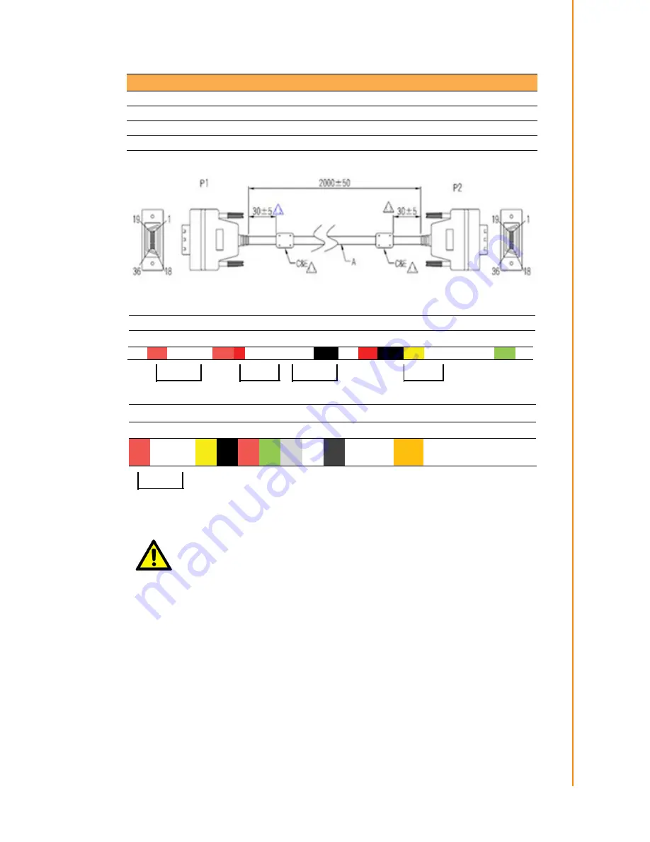
in Assignments
Figure 3.2 Smart Display Cable Diagram
Table 3.2: Ordering Information for Smart Display Cable (Optional)
P/N
Description
1700020007
M Cable SCSI 36P(M)/SCSI 36P(M) 200cm (LVDS Cable)
1700020008
M Cable SCSI 36P(M)/SCSI 36P(M) 500cm (LVDS Cable)
1700020329-01
M Cable SCSI 36P(M)/SCSI 36P(M) 800cm (LVDS Cable)
Caution!
To assure signal quality, the maximum cable length is limited to 10-
meters. If longer cable length is desired, an additional signal booster box
might be required. Please contact Advantech for further assistance.
P1 1 2 3
4 5 6 7
8 9 10
11
12
13
14
15 16 17
18
P2 1 2 3
4
5 6 7
8 9 10 11 12 13 14 15
16
17 18
Color Brown White Ground Brown red white Ground Ground
white red
yellow white Ground Ground Green white
Blue
white Ground
yellow
Blue
Purple
Grey white Black
Black black
Brown red
Orange
Black Black Black Black Black
Yellow green
blue
purple
grey
19 20 21 22 23 24 25 26 27 28 29 30 31
32 33 34 35 36
19 20 21 22 23 24 25 26 27 28 29 30 31
32 33 34 35 36
Summary of Contents for TREK-306DH
Page 1: ...User Manual TREK 306DH 10 4 In Vehicle Smart Display...
Page 8: ...TREK 306DH User Manual viii...
Page 18: ...TREK 306DH User Manual 10...
Page 22: ...TREK 306DH User Manual 14...
Page 26: ...TREK 306DH User Manual 18...


