9
TREK-550/303 User Manual
Chapter 2
S
ystem
Setup
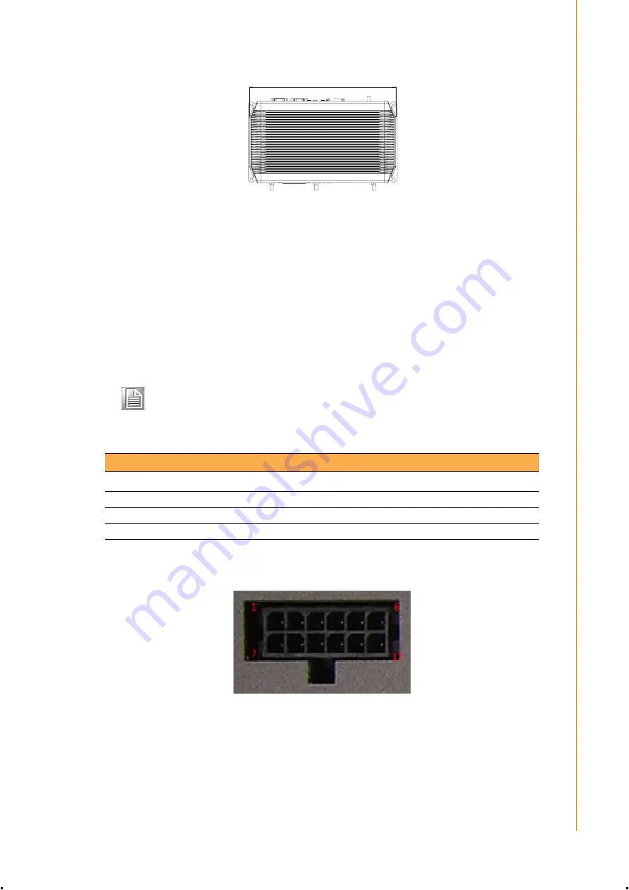
Figure 2.5 Top view of TREK-550
2.2 Installation Procedures
2.2.1 Connecting the Power Cord
Connect the three pin waterproof power cord to the DC inlet of the In-Vehicle Com-
puting Box. On the open-wire end, one pin is reserved for positive voltage and is
marked, "+"; one pin is reserved for ground and is marked, "-"; and, one pin is
reserved for the ignition signal with an “ignition” mark.
2.2.2 Power Connector
Figure 2.6 Power connector outlook
266
Unit: mm
Note!
Ignition on/off setting: The TREK-550 supports an ignition on/off function
so that you can power on/off the TREK-550 via the ignition signal/volt-
age and connect the TREK-550 vehicle ignition switch.
Table 2.1: Pin Definition of Power Cord
Pin
Definition
Color
1
+
Red
3
-
Black
4
Ignition
Orange
Summary of Contents for TREK-303
Page 1: ...User Manual TREK 550 TREK 303 In Vehicle Computing Box Smart Display ...
Page 8: ...TREK 550 303 User Manual viii ...
Page 12: ...TREK 550 303 User Manual xii ...
Page 18: ...TREK 550 303 User Manual 6 ...
Page 24: ...TREK 550 303 User Manual 12 ...
Page 40: ...TREK 550 303 User Manual 28 ...
Page 51: ...Appendix A A TREK 303 This appendix explains the TREK 303 detailed information ...


