background image

11

POC-W243L Series User Manual

Chapter 2

S

ystem

Setup

2.2.2

Connecting the Ground pin

1.

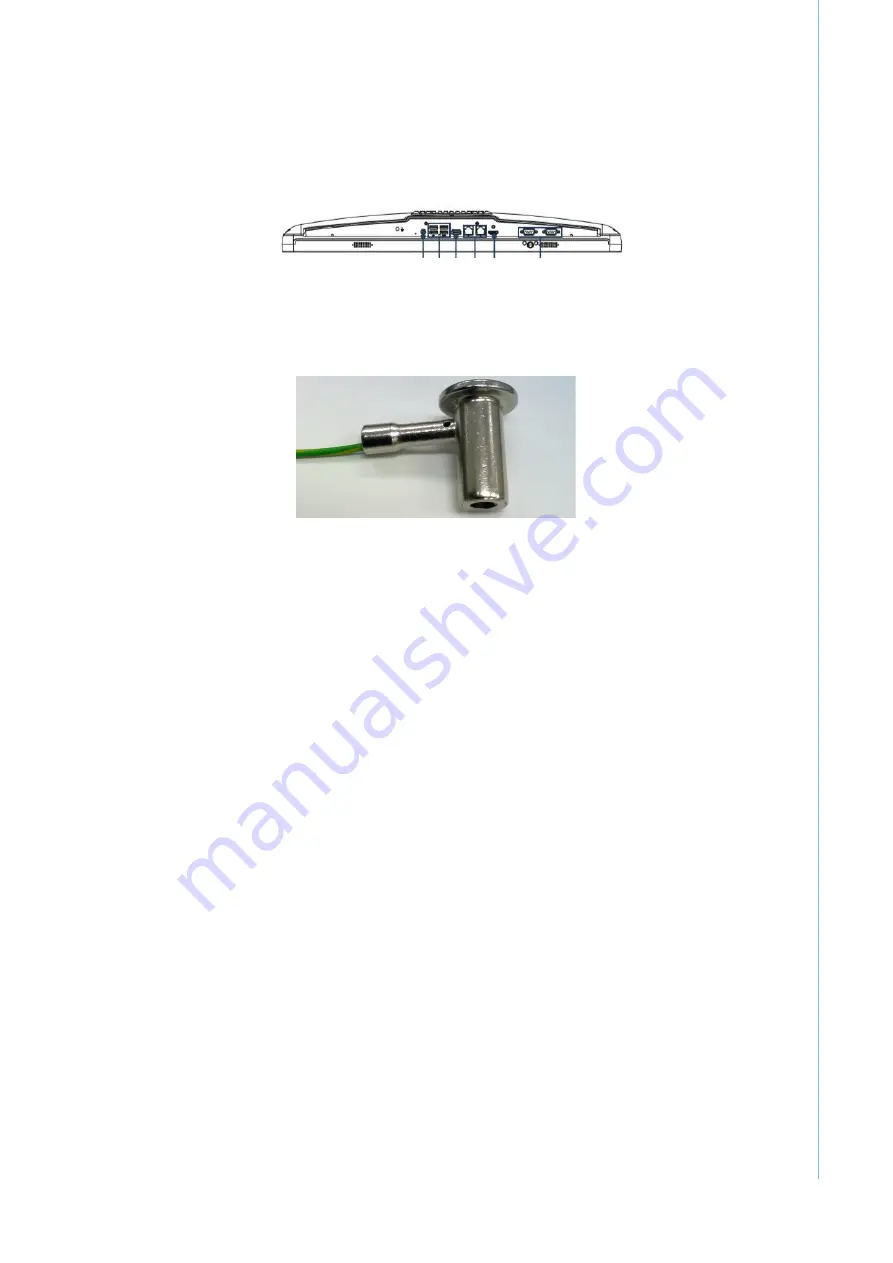
To get the system ready, find the Equipotential Terminal on rear side of POC. An 
Equipotential Terminal is provided to optionally connect to a hospital ground/
earth system.

Figure 2.5 POC-W243L Series Equipotential Terminal Pin

2.

Prepare the grounding cable and the other terminal link to hospital’s ground/
earth system.

Figure 2.6 Grounding cable with connector

3.

Grounding cable plug with POC-W243L series Equipotential Terminal  (See Fig-
ure 2.5)

2.3

Running the BIOS Setup Program

Your POC-W243L series was probably set up and configured by your dealer prior to
delivery. You may still find it necessary to use the BIOS (Basic Input-Output System)
setup program to change system configuration information, such as the current date
and time or your type of hard drive. The setup program is stored in read-only mem-
ory. It can be accessed either when you turn on or reset the panel PC, by pressing
the "F2 or Del" key on your keyboard immediately after powering on the computer.
The settings you specify with the setup program are recorded in a special area of
memory called CMOS RAM. This memory is backed up by a battery so that it will not
be erased when you turn off or reset the system. Whenever you turn on the power,
the system reads the settings stored in CMOS RAM and compares them to the
equipment check conducted during the power on self-test (POST). If an error occurs,
an error message will be displayed on screen, and you will be prompted to run the
setup program.

Summary of Contents for POC-W243L Series

Page 1: ...User Manual POC W243L Series Point of Care Terminal with Intel Core i7 i5 i3 and Celeron Processor and a 23 8 TFT LCD...

Page 2: ...manual and on labels on the equipment 3 Repair of the device may also only be carried out by trained service personnel Advantech recommends that a service contract be obtained with Advantech Service a...

Page 3: ...e power source to avoid damage by transient over voltage 8 If your computer is losing dramatic time or the BIOS configuration reset to default the battery has no power Caution To avoid short circuitin...

Page 4: ...otection follow national requirements to dispose of unit 12 Maintenance properly maintain and clean the surfaces use only the approved products or clean with a dry applicator 13 Make sure the user doe...

Page 5: ...raged to try to correct the interference by one or more of the following measures Reorient or relocate the receiving antenna Increase the separation between the equipment and the receiver Connect the...

Page 6: ...f the problem The exact wording of any error messages This equipment is a source of electromagnetic waves Before use please make sure that there are not EMI sensitive devices in its surrounding which...

Page 7: ...rminal 8 2 1 2 Rear View 9 Figure 2 2 Rear view of the Point of Care Terminal 9 Figure 2 3 Rear view of Multi I O ports 9 2 2 Installation Procedures 10 2 2 1 Connecting the power cord 10 Figure 2 4 C...

Page 8: ...POC W243L Series User Manual viii...

Page 9: ...Chapter 1 1 General Information...

Page 10: ...ts or appliances http support advantech com tw support 1 2 Specifications Computing System CPU Intel Kaby Lake Core i5 7300U Celeron 3965U Memory 1 x DDR4 SODIMM slot Default 4GB Up to 16GB Primary St...

Page 11: ...Temperature Operating 0 C 40 C Storage 20 C 60 C Humidity Operating 10 90 40 C non con densed Storage 5 90 40 C non con densed Shock Resistance 20G peak acceleration 11ms duration Pressure 700 1013 h...

Page 12: ...583 x 386 x 69 mm Unit mm Figure 1 1 Dimensions of the POC W243L series VESA Mounting 75 x 75 mm 100 x 100 mm Please use M4x12L Maximum screw Figure 1 2 VESA Mounting of the POC W243L Series Warning...

Page 13: ...fecting During normal use of the POC Point of Care Terminal the device may become dirty and should be regularly cleaned Steps 1 Prepare cleaning agent per manufacturer s instructions or hospital proto...

Page 14: ...l Do not autoclave or clean the POC or its peripherals with strong aromatic chlorinated ketone ether or Esther solvents sharp tools or abrasives Never immerse electrical connectors in water or other l...

Page 15: ...Chapter 2 2 System Setup...

Page 16: ...on and purpose of the controls drives connections and ports which are illustrated in the figures below When you place the POC W243L series upright on the desktop its front panel appears as shown in Fi...

Page 17: ...the bottom of the panel PC as shown in Figure 2 2 and zoom in Figure 2 3 The I O section includes various I O ports Ethernet port USB ports and so on Figure 2 2 Rear view of the Point of Care Termina...

Page 18: ...er to the DC jack of the panel PC see Figure 2 4 2 Connect the female end of the power cord to the DC power adapter 3 Connect the 3 pin male plug of the power cord to an electrical outlet Figure 2 4 C...

Page 19: ...ind it necessary to use the BIOS Basic Input Output System setup program to change system configuration information such as the current date and time or your type of hard drive The setup program is st...

Page 20: ...nd installation of the operating system 2 5 Installing the Drivers After installing your system software you will be able to set up the Chipset Graphics Ethernet audio and touchscreen functions from y...

Page 21: ...Manual Chapter 2 System Setup Description of your software operating system version application software etc A complete description of the problem The exact wording of any error messages Symptoms pho...

Page 22: ...POC W243L Series User Manual 14...

Page 23: ...Chapter 3 3 Operation and Safety...

Page 24: ...he drive when you re not using it Do not put anything on the drive tray when it is open Do not touch the optical drive lens with your fingers Do not wipe the lens with a paper towel or other abrasive...

Page 25: ...If you are unable to insert the plug into an outlet because the outlet is not grounded contact a licensed electrician to replace the outlet with a properly grounded outlet Do not defeat the purpose o...

Page 26: ...POC W243L Series User Manual 18...

Page 27: ...Appendix A A POC W243L Series VESA Mounting...

Page 28: ...should be carried out by a professional technician please contact a service technician or your retailer if you need this service Installation instructions follow 1 First attach wall mounting to the He...

Page 29: ...21 POC W243L Series User Manual Appendix A POC W243L Series VESA Mounting...

Page 30: ...tions are subject to change without notice No part of this publication may be reproduced in any form or by any means electronic photocopying recording or otherwise without prior written permis sion of...

Reviews: