


PCM-9575 User’s Manual
22
2.21 Ethernet configuration
The PCM-9575 is equipped with a high performance 32-bit PCI-bus
Ethernet interface which is fully compliant with IEEE 802.3U 10/
100Mbps CSMA/CD standards. It is supported by all major network
operating systems.
The medium type can be configured via the RSET8139.EXE program
included on the utility disk. (See Chapter 3 for detailed information.)
2.21.1 100Base-T connector (CN12)
10/100Base-T connects to the PCM-9575 via an adapter cable to a 10-pin
polarized header (CN12).
2.21.2 Network boot
The Network Boot feature can be utilized by incorporating the Boot
ROM image files for the appropriate network operating system. The Boot
ROM BIOS files are included in the system BIOS, which is on the utility
CD disc.
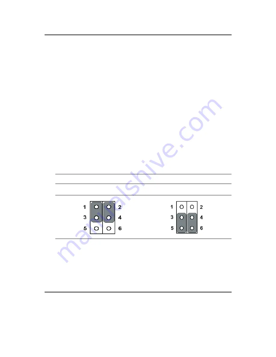
2.21.3 LAN controller power select (JP2)
Note: PCM-9575 supports Wake-on-LAN. For Wake-on LAN, J6 has to
be set to the Standby 3.3 V position
2.22 Watchdog timer configuration
An on-board watchdog timer reduces the chance of disruptions which
EMP (electro-magnetic pulse) interference can cause. This is an invalu-
able protective device for standalone or unmanned applications. Setup
Table 2.5: LAN controller power select (JP2)
3.3 V*
Standby 3.3V
* default setting
Summary of Contents for PCM-9575
Page 1: ...i PCM 9575 EBX VIA Eden Ezra SBC with CPU LCD Ethernet Audio PCI and PC 104 Plus Users Manual...
Page 4: ...PCM 9575 User s Manual iv...
Page 10: ...x...
Page 16: ...PCM 9575 User s Manual 6 1 4 Board layout dimensions Figure 1 1 Board layout dimensions...
Page 20: ...PCM 9575 User s Manual 10 2 3 Locating jumpers Figure 2 1 Jumper locations...
Page 21: ...11 Chapter 2 Installation 2 4 Locating Connectors Figure 2 2 Connectors component side...
Page 34: ...PCM 9575 User s Manual 24...
Page 41: ...31 Chapter 3 Software Configuration Note For Ethernet installation please see Chapter 7...
Page 42: ...PCM 9575 User s Manual 32...
Page 63: ...53 Chapter 5 PCI SVGA Setup Step 2 Select Adapter then Change...
Page 68: ...PCM 9575 User s Manual 58 Step 2 Choose the Settings tab and press the Display Type button...
Page 69: ...59 Chapter 5 PCI SVGA Setup Step 3 Press the Change button...
Page 73: ...63 Chapter 5 PCI SVGA Setup Step 2 Choose the Video Controller VGA Compatible button...
Page 74: ...PCM 9575 User s Manual 64 Step 3 Choose the Drive button press Update Driver button...
Page 78: ...PCM 9575 User s Manual 68 Step 2 Choose Hardware and Device Manager press OK button...
Page 79: ...69 Chapter 5 PCI SVGA Setup Step 3 Choose Video Controller VGA Compatible press OK but ton...
Page 84: ...PCM 9575 User s Manual 74...
Page 101: ...91 Chapter 6 Audio Setup Step 8 Press Next button Step 9 Press Finish to reboot...
Page 102: ...PCM 9575 User s Manual 92...
Page 108: ...PCM 9575 User s Manual 98 7 2 3 Installation for Windows 2000 Step 1 Open Device Manager...
Page 109: ...99 Chapter 7 PCI Bus Ethernet Interface Step 2...
Page 110: ...PCM 9575 User s Manual 100 Step 3 Step 4...
Page 111: ...101 Chapter 7 PCI Bus Ethernet Interface Step 5 Step 6...
Page 112: ...PCM 9575 User s Manual 102 Step 7 Step 8...
Page 114: ...PCM 9575 User s Manual 104 b Click Next Step 3 a Click Select from list...
Page 116: ...PCM 9575 User s Manual 106 Step 6 Check the highlighted item and click OK...
Page 120: ...PCM 9575 User s Manual 110...
Page 124: ...TPC 642 User s Manual 114...
Page 127: ...117 Appx B Figure B 1 PC 104 module mounting diagram...
Page 128: ...TPC 642 User s Manual 118 Figure B 2 PC 104 module dimensions mm 0 1...
Page 150: ...PCA 6183 User s Manual 140...
Page 155: ...145 Appx E E Optional Extras for the PCM 9575 Appendix...
Page 158: ...PCM 9575 User s Manual 148...
Page 159: ...149 Appx F F Mechanical Drawings Appendix...
Page 161: ...151 Appx F Figure F 2 PCM 9575 Mechanical Drawing component side...
Page 162: ...PCM 9575 User s Manual 152 Figure F 3 PCM 9575 Mechanical Drawing solder side...


