


MIC-7900 User Manual
8
2.1
Introduction
The following sections show the internal jumper settings and the external connectors
and pins assignment for applications.
2.2
Jumpers
2.2.1
Jumper Description
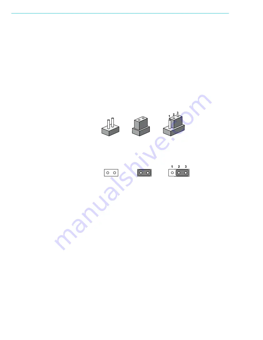
You may configure the MIC-7900 to match the needs of your application by setting
jumpers. A jumper is a metal bridge used to close an electric circuit. It consists of two
metal pins and a small metal clip (often protected by a plastic cover) that slides over
the pins to connect them. To close a jumper, you connect the pins with the clip. To
open a jumper, you remove the clip. Sometimes a jumper will have three pins,
labelled 1, 2 and 3. In this case you would connect either pins 1 and 2, or 2 and 3.
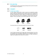
The jumper settings are schematically depicted in this manual as follows.
A pair of needle-nose pliers may be helpful when working with jumpers. If you have
any doubts about the best hardware configuration for your application, contact your
local distributor or sales representative before you make any changes. Generally, you
simply need a standard cable to make most connections.
closed 2-3
closed
open
1
2
1
2
closed 2-3
closed
open
Summary of Contents for MIC-7900
Page 1: ...User Manual MIC 7900 Embedded Fan less IPC System 866 412 6278 CoastIPC com...
Page 11: ...Chapter 1 1 General Introduction This chapter gives background information on MIC 7900...
Page 16: ...MIC 7900 User Manual 6...
Page 28: ...MIC 7900 User Manual 18...
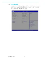
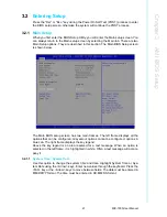
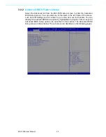
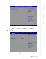
Page 29: ...Chapter 3 3 AMI BIOS Setup This chapter introduces how to set BIOS configuration data...
Page 77: ...Chapter 4 4 Software Installation This chapter introduces driver installation...
Page 82: ...MIC 7900 User Manual 72...
Page 83: ...Appendix A A Programming the Watchdog Timer...


