


Web GUI Monitoring & Control
4.3.2
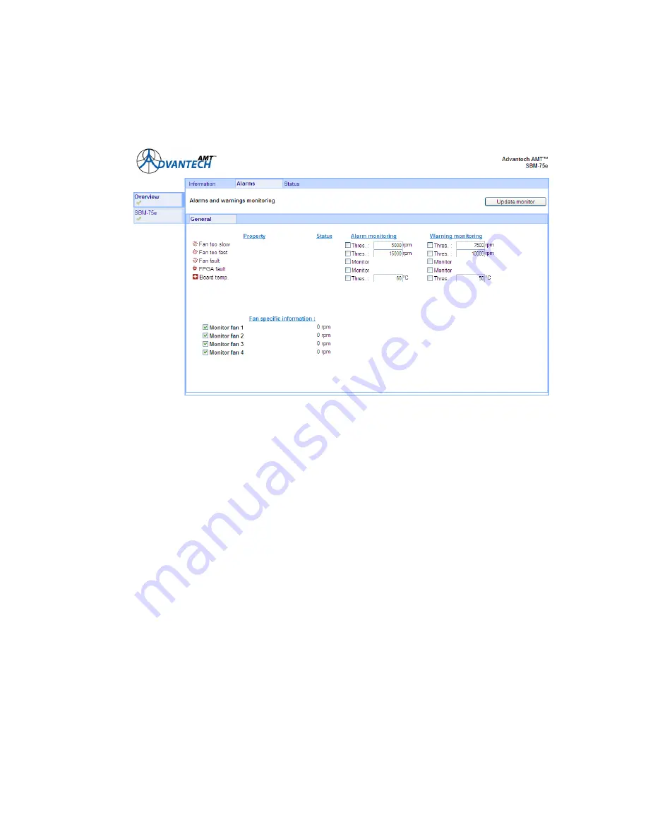
Overview: Alarms
The alarm status of the units displayed in
Figure 4.2
may be viewed by selecting the Alarms tab. A
window similar to the one shown in
Figure 4.3
is displayed.
Figure 4.3: Alarms and Warnings Monitoring Window
In this window each of the properties listed may be monitored on two levels - alarm or warning.
The thresholds of some of these properties are adjustable by the user. The Status column shows
that the ‘Fan Fault’ alarm status is satisfactory i.e. warning monitoring is not being performed for
this property, and that ‘Board Temp’ alarm and warning monitoring are also satisfactory.
An example is given below to illustrate the process of applying monitoring to other properties on
the window.
To apply ‘Fan too fast’ monitoring to fan number 2:
1.
Check the Alarm and Warning boxes in the appropriate row of the window shown above.
2.
Check the ‘Monitor Fan 2’ box.
3.
Select the ‘Update Monitor’ tab on the top right-hand side of the window. A window similar
to the one shown in
Figure 4.4
is displayed.
SBM75e Series Modulator Installation and Operation Manual
4-5
Summary of Contents for L-Band Satellite Modulator
Page 14: ...Getting Started 1 8 SBM75e Series Modulator Installation and Operation Manual...
Page 45: ...Front Panel Monitoring Control SBM75e Series Modulator Installation and Operation Manual 3 15...
Page 73: ...Web GUI Monitoring Control 4 28 SBM75e Series Modulator Installation and Operation Manual...
Page 78: ...Technical Specification SBM75e Series Modulator Installation and Operation Manual A 5...
Page 90: ...Glossary B 12 SBM75e Series Modulator Installation and Operation Manual...


