ITA-2230S Startup Manual 7
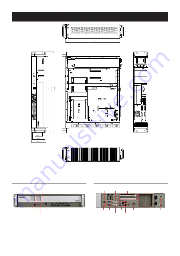
Rear IO View
PS/2
DVI-D
PCI/PCIe x 4 Interface
ITAM
Power LED
Alarm LED
COM
DVI-I
USB
LAN
DIO
Power
Front Panel View
COM LED
Power Button
Reset Button
HDD LED LAN LED
System Diagram
Page 1: ...D or 2 x 2 5 HDD 1 x Full Size mSATA Expansion slot 2 x ITAM slot 1 x PC104 1 x Mini PCIe slot 1 x PCI slot 1 x PCIE x4 slot System Specifications Ethernet 2 x 10 100 1000M Ethernet USB 4 USB 3 0 3 US...
Page 2: ...g 1 2 Default 2 3 Clear CMOS setting Default setting Default Clear CMOS PSON1 Power On Mode Setting Pins Setting 1 2 AT mode 2 3 ATX mode Default setting AT Mode ATX Mode VCCGPIO1 GPIO Voltage Setting...
Page 3: ...ical Sync 23 T M D S Clock 9 T M D S Data1 24 T M D S Clock 10 T M D S Data1 C1 Analog Red 11 T M D S Data1 3 Shield C2 Analog Green 12 T M D S Data3 C3 Analog Blue 13 T M D S Data3 C4 Analog Horizont...
Page 4: ...ge device LED Orange Power LED Green Warning LED Red The system has 3 indicator LEDs at right ahead with LEDs showing network status LED Color Status Storage device LED Orange Power LED Green Warning...
Page 5: ...ver the power cord 9 All cautions and warnings on the equipment should be noted 10 If unused for a long time disconnect the equipment from the power source to avoid damage from transient overvoltages...
Page 6: ...r Setting Drawing Mainboard Jumpers and Connectors Location Backplane Jumpers and Connectors Location mSATA Slot USB 7 8 SATA 2 0 SATA 3 0 PSON1 SATA PWR mini PCIe Slot JCMOS1 LPT1 VIO1 PC104_ISA PC10...
Page 7: ...tartup Manual 7 Rear IO View PS 2 DVI D PCI PCIe x 4 Interface ITAM Power LED Alarm LED COM DVI I USB LAN DIO Power Front Panel View Alarm LED COM LED Power Button Reset Button USB HDD LED LAN LED Sys...