background image

v

Contents

Chapter

1 General Information ....................................... 2

1.1

Introduction ....................................................................... 2

1.2

Specifications .................................................................... 2

1.2.1

General ........................................................................... 2

1.2.2

System Hardware ........................................................... 3

1.2.4

Environment ................................................................... 3

1.3

IPPC-4001 Series List ....................................................... 4

1.4

Dimensions........................................................................ 4

1.5

Exploded Diagram............................................................. 5

Figure 1.1:Exploded Diagram ........................................ 5

1.6

Accessory Packing list ...................................................... 5

Chapter

2 System Setup.................................................... 8

2.1

System Installation  ........................................................... 8

2.1.1

Attaching the Handles .................................................... 8

2.1.2

Removing the Top Cover ............................................... 8

2.1.3

Chassis Front and Rear Sections .................................... 9

2.1.4

Drive Bay Installation .................................................. 11

2.1.5

Motherboard Installation & Information  ..................... 11

2.2

LED Indicators ................................................................ 12

2.2.1

System Status LED  ...................................................... 12

2.2.2

Power Status LED ........................................................ 13

2.3

Power Supply .................................................................. 13

2.4

Cooling Fan & Filter ....................................................... 14

Chapter

3 Alarm Board .................................................. 16

3.1

Alarm Board Layout........................................................ 16

3.2

Alarm Board Specification.............................................. 17

3.3

Switch Setting ................................................................. 21

3.4

Thermal Sensor ............................................................... 22

Summary of Contents for IPPC-4001 Series

Page 1: ...i IPPC 4001 Series 5 7 VGA TFT LCD 4U 19 Rack Industrial Panel PC with 14 Expansion Slots Keyboard Drawer Users Manual...

Page 2: ...ansmit ted in any form or by any means without the prior written permission of Advantech Co Ltd Information provided in this manual is intended to be accurate and reliable However Advantech Co Ltd ass...

Page 3: ...dential area is likely to cause harmful inter ference in which case the user will be required to correct the interference at his own expense Additional Information and Assistance Step 1 Visit the Adva...

Page 4: ...y liquid into an opening This may cause fire or electrical shock 13 Never open the equipment For safety reasons the equipment should be opened only by qualified service personnel 14 If one of the foll...

Page 5: ...ter 2 System Setup 8 2 1 System Installation 8 2 1 1 Attaching the Handles 8 2 1 2 Removing the Top Cover 8 2 1 3 Chassis Front and Rear Sections 9 2 1 4 Drive Bay Installation 11 2 1 5 Motherboard In...

Page 6: ...IPPC 4001 User Manual vi...

Page 7: ...1 Chapter1 CHAPTER 1 General Information...

Page 8: ...ck mount IA Master supports system fault detection The web enabled and webbased alarm notification system monitors system status including SBC status voltages power supply cooling fans and temperature...

Page 9: ...Backlight Life 50 000 hrs LED Backlight Contrast Ratio 300 1 Display Size 5 7 Display Type QVGA TFT LCD Luminance 220 cd m2 Max Colors 262 K RGB 6 bit Max Resolution 640 x 480 OSD Control ON OFF Brigh...

Page 10: ...IPPC 4001 User Manual 4 1 3 Dimensions...

Page 11: ...5 Chapter2 CHAPTER 2 System Setup...

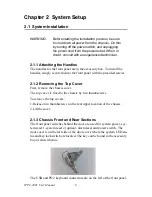
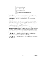
Page 12: ...cover 2 1 3 Chassis Front and Rear Sections The front panel switches behind the door are used for system power sys tem reset 1 system reset 2 option alarm reset and power switch The door cover is on t...

Page 13: ...ltage problem an audiblealarm is activated Pressing this switch will cause the alarm to stop Power On Off Switch Use this switch to turn on off the system power Momentary Switch Use this switch and by...

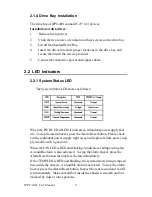
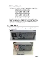
Page 14: ...icates a redundant power supply fail ure To stop the alarm buzzer press the Alarm Reset button Please check out the redundant power supply right away and replace failure power sup ply module with a go...

Page 15: ...it indicates a problem with one of the voltage signals An audible alarm is sounded Check to make sure that the power supply connector is properly attached to the backplane If problem per sists consul...

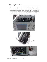
Page 16: ...system sounds a continuous alarm To disable the alarm press the Alarm Reset switch and replace the fan immediately To replace a defective fan refer to the figures below Press location A and then pull...

Page 17: ...11 Chapter3 CHAPTER 3 Alarm Board...

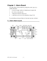
Page 18: ...ives an audible alarm when 1 Any power supply module of redundant power supply fails 2 One of the cooling fans fai1s 3 Temperature inside the chassis rises 4 A problem occurs in one of the backplane v...

Page 19: ...nnect from CPU card One system reset connector connect from CPU card One Hard Disk LED connector connect from CPU card Output Signals One LED board connector One LCM board connector SNMP daughter boar...

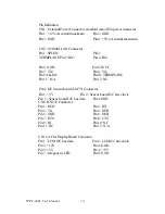
Page 20: ...CC Pin7 TX Pin 8 TX Pin9 LILED Pin10 TERMPLANE Pin 11 N A Pin12 NC CN4 I2C Sensor board LM75 Connector Pin1 5V Pin 2 Sensor board I2C bus clock Pin 3 Sensor board I2C bus data Pin4 GND CN8 RS 232Conne...

Page 21: ...3 TX Pin24 NC Pin25 TX Pin 26 NC Pin27 RX Pin28 NC Pin29 RX Pin30 NC Pin31 TERMPLANE Pin32 NC CN12 SNMP 1000 Daughter Board Connector Right side Pin1 NC Pin2 NC Pin 3 Power Good A Pin4 NC Pin5 NC Pin6...

Page 22: ...PowerFail Signal Pin 9 Temperature Good Signal Pin 10 Temperature Fail Signal Pin 11 Fan Good Signal Pin 12 FAN Fail Signal Pin13 NC Pin14 3 3VSignal Pin15 5VSBSignal CN19 Connector bank from CPU car...

Page 23: ...17 Chapter3 3 3 Switch Setting Fan Number Setting Thermal Board Temperature Setting...

Page 24: ...IPPC 4001 User Manual 18...

Reviews: