


IPC-6806S User Manual
18
Chapter 3 Operation
3.1 The Front Section of IPC-6806S
3.1.1 Switches
Two switches are used for system power on-off and system reset.
•
System Reset Switch
: Press this switch to reinitialize the system.
•
Power On-Off Switch
: Use this switch to turn on/off the system power.
3.1.2 LED indicators
Two LEDs are placed to indicate the system status. Please refer to Table
3-1 for the LED summary.
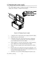
If the system is connected with a single power supply, the PWR LED is
always Green when power on.
Table 3.1: System status LED summary
LED
Description
Green/Orange
PWR
System Power
Normal
HDD
Hard Drive Disk Activity
Read/Write Data
Summary of Contents for IPC-6806S
Page 1: ...IPC 6806S Wallmount IPC Chassis for 6 Half sized Cards User Manual...
Page 10: ...IPC 6806S User Manual iv B 2 2 Connectors 28 B 2 3 Connector Pin Definition 28...
Page 11: ...2 CHAPTER 1 General Information...
Page 14: ...IPC 6806S User Manual 4 1 6 Dimensions of IPC 6806S Figure 1 1 Dimensions of IPC 6806S...
Page 15: ...5 Chapter1 Figure 1 2 Details of wallmount brackets...
Page 16: ...IPC 6806S User Manual 6...
Page 17: ...2 CHAPTER 2 System Setup...
Page 26: ...IPC 6806S User Manual 16...
Page 27: ...2 CHAPTER 3 Operation...
Page 31: ...2 APPENDIX A Exploded Diagram...
Page 32: ...IPC 6806S User Manual 22 Appendix A Exploded Diagram Figure A 1 Exploded Diagram...
Page 33: ...2 APPENDIX B Passive Backplanes...
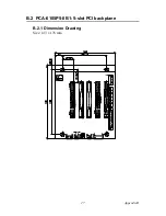
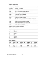
Page 37: ...27 AppendixB B 2 PCA 6105P5 0B1 5 slot PCI backplane B 2 1 Dimension Drawing Size 143 x 176 mm...
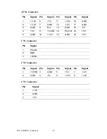
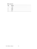
Page 40: ...IPC 6806S User Manual 30 BIG1 Connector Pin Signal 1 12V 2 GND 3 GND 4 5V...


