iDAQ-900 User Manual
8
2.1
Installation
iDAQ-934/iDAQ-938
After the device drivers are installed, the iDAQ-934/iDAQ-938
chassis can be
installed in the computer.
1.
Touch any metal surface of the computer to discharge any static electricity that
may be in your body.
2.
Insert the USB cable into the designated USB port.
After the chassis and iDAQ modules are installed, the device can be configured using
the Advantech Navigator Program automatically installed during driver setup. Note
that the iDAQ modules would only be recognized when the module is inserted in the
iDAQ chassis.
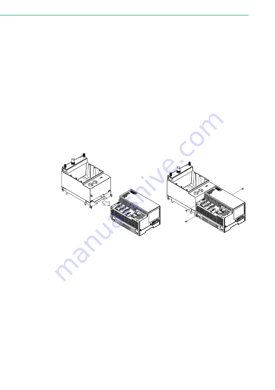
iDAQ-964
The iDAQ-964 should be used along with AMAX-5000 system. Here we take AMAX-
5580 as an example. The assembly procedure is as follows:
1.
Insert the PCI express BUS into the AMAX system.
2.
Tighten the three screws around the connection on the AMAX-5580.
Figure 2.1 Installation Guide of iDAQ-964
Summary of Contents for iDAQ-900 Series
Page 1: ...User Manual iDAQ 900 Series iDAQ 934 iDAQ 938 iDAQ 964 Industrial DAQ Chassis ...
Page 10: ...iDAQ 900 User Manual x ...
Page 11: ...Chapter 1 1 Start Using iDAQ Chassis ...
Page 17: ...Chapter 2 2 Installation Guide ...
Page 21: ...11 iDAQ 900 User Manual Chapter 2 Installation Guide ...
Page 24: ...iDAQ 900 User Manual 14 ...
Page 25: ...Chapter 3 3 Function Details ...
Page 46: ...iDAQ 900 User Manual 36 ...
Page 47: ...Appendix A A Specifications ...
Page 50: ...iDAQ 900 User Manual 40 A 8 Function Block iDAQ 934 iDAQ 964 iDAQ 938 ...
Page 51: ...Appendix B B System Dimensions ...
Page 52: ...iDAQ 900 User Manual 42 B 1 Chassis iDAQ 934 ...
Page 53: ...43 iDAQ 900 User Manual Appendix B System Dimensions iDAQ 964 iDAQ 938 ...
Page 54: ...iDAQ 900 User Manual 44 B 2 Mounting Wall Mount for iDAQ 934 Wall Mount for iDAQ 938 ...
Page 55: ...45 iDAQ 900 User Manual Appendix B System Dimensions ...


