


FPM-8192V/8232V User Manual
16
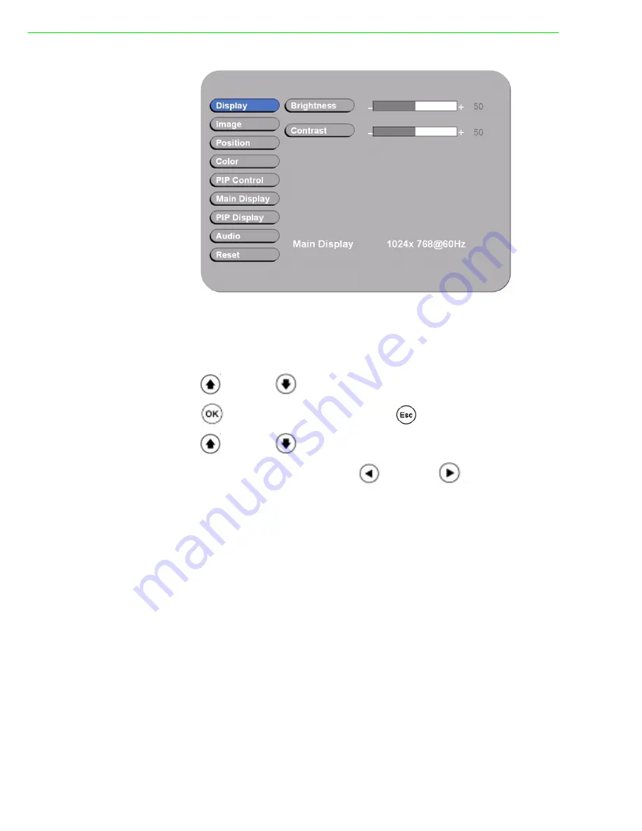
Figure 3.2 OSD Menu
There are 9 functions for in the OSD Menu for selection. For each function, it is very
easy to select by the other navigation keys to adjust. Following the direction as
below:
1. Press “
” (Up) and “
” (Down) to select each function.
2. Press “
” to enter the sub menu, and press “
” to exit.
3. Press “
” (Up) and “
” (Down) to select the sub-function.
4. When enter to each sub-function, press “
” (Left) and “
” (Right) to decrease
/ increase the bar value.
Summary of Contents for FPM-8192V
Page 1: ...User Manual FPM 8192V 8232V 19 23 Marine Grade Monitors...
Page 6: ...FPM 8192V 8232V User Manual vi...
Page 9: ...Chapter 1 1 General Information...
Page 14: ...FPM 8192V 8232V User Manual 6...
Page 15: ...Chapter 2 2 Installation...
Page 18: ...FPM 8192V 8232V User Manual 10 Note VESA and wall mount with mounting kit by special request...
Page 20: ...FPM 8192V 8232V User Manual 12...
Page 21: ...Chapter 3 3 Operating the LCD Display...
Page 35: ...Appendix A A Cleaning the Monitor...
Page 37: ...Appendix B B Troubleshooting...
Page 39: ...Appendix C C Supported Modes...
Page 41: ...Appendix D D RS 232 Command Code Optional...


