9
DSPC-8661-PCXE User Manual
Chapter 1
Introduction
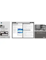
1.7.2.3
JTAG Debug Port
The JTAG debug port connects with the JTAG debug board (optional) for software
programming and debugging.
1.7.2.4
DIO & Control Port
The DIO & control port connects with the DIO & control board (optional) through I2C
and UART for providing:
16x DI + 8x DO
RS485
Pin number
Pin signal
Pin number
Pin signal
1
TMS
2
TRSTn
3
TDI
4
GND
5
VCC_3V3
6
7
TDO
8
GND
9
RTCK
10
GND
11
TCK
12
GND
13
EMU0
14
EMU1
15
EMU_RSTn
16
GND
17
EMU2
18
EMU3
19
EMU4
20
GND
21
NA
22
NA
23
UART_RXD
24
UART_TXD
25
26
VCC_3V3
Pin number
Pin signal
Pin number
Pin signal
1
UART1_TXD
2
VCC_5V
3
UART1_RXD
4
VCC_5V
5
RS485_DIR
6
GND
7
IIC1_SCL
8
VCC_3V3
9
IIC1_SDA
10
9555_INTn
Summary of Contents for DSPC-8661-PCXE
Page 1: ...User Manual DSPC 8661 PCXE...
Page 6: ...DSPC 8661 PCXE User Manual vi...
Page 8: ...DSPC 8661 PCXE User Manual viii...
Page 9: ...Chapter 1 1 Introduction...
Page 25: ...Chapter 2 2 Linux Demo Program...
Page 30: ...DSPC 8661 PCXE User Manual 22...
Page 31: ...Chapter 3 3 Windows Driver Installation For Windows XP For Windows Vista For Windows 7...
Page 44: ...DSPC 8661 PCXE User Manual 36...
Page 45: ...Chapter 4 4 Firmware Loader for Windows...
Page 51: ...43 DSPC 8661 PCXE User Manual Chapter 4 Firmware Loader for Windows...