Operation
8
LED
STATUS
FUNCTION
Power
Red
Solid:
Power applied.
RSSI
Tri-color
Off:
Red:
Yellow:
Green:
No radio signal.
Weak radio signal.
OK radio signal.
Strong radio signal.
RF Data
Green
Off:
Blinking:
No radio link data.
Radio link data TD/RD traffic.
Bus
Green
Off:
Blinking:
No local bus data.
Local bus data TD/RD traffic.
PEER-to-PEER MODE
Hardware Installation
2
Modbus Mode - continued:
Configure Wireless Settings:
Select the desired RF Transmit Power.
Select the desired OTA data rate (not applicable for -SR models).
Set the Channel Number to match the Modbus radio modem you will be
communicating with.
Set the Network Identifier to match the Modbus radio modem you will
be communicating with.
If using a Model ZP9D-115RM-LR radio modem, set the destination
address (ATDT) to 0xFFFF.
Set Repeater checkbox if the base is to be a repeater. Note that ONLY
long-range Models ZZ9D-NA-LR and ZZ9D-NB-LR support this.
Select encryption.
Click Update to save configuration.
Refer to the User Manual for more details concerning wireless settings.
Configure Input/Output
7
Set Analog Inputs and Analog Outputs for 0 to 10 VDC or 0 to 20 mA as
required (setting one sets all analog I/O for that module).
Set Digital Inputs for Discrete or Counter, as required.
Check
Enabled
checkbox and set appropriate values for parameters in
Exception Reporting
section to use the ability of reporting possible
problems on devices.
Set Calibration option if you desire to better match a sensor, or a portion
of a signal, to the I/O.
Check
Enabled
checkbox and set appropriate values for parameters in
Failsafe section to go to the user-defined values for AO or DO in case
of communication failure.
Check
Use Output to Indicate Communication Failure
checkbox in
D
edicated Comm Fail Alarm
section to configure the first DO on the
base module to be a communication failure alarm indicator.
Check
Invert Output
checkbox to invert the logic of Digital Outputs on
base or expansion modules.
Click Update button to apply the settings.
Refer to Troubleshooting section of User Manual if
operation is not sucessful.
Select Modules
1
Select the base and expansion modules required for the location and
coverage distances.
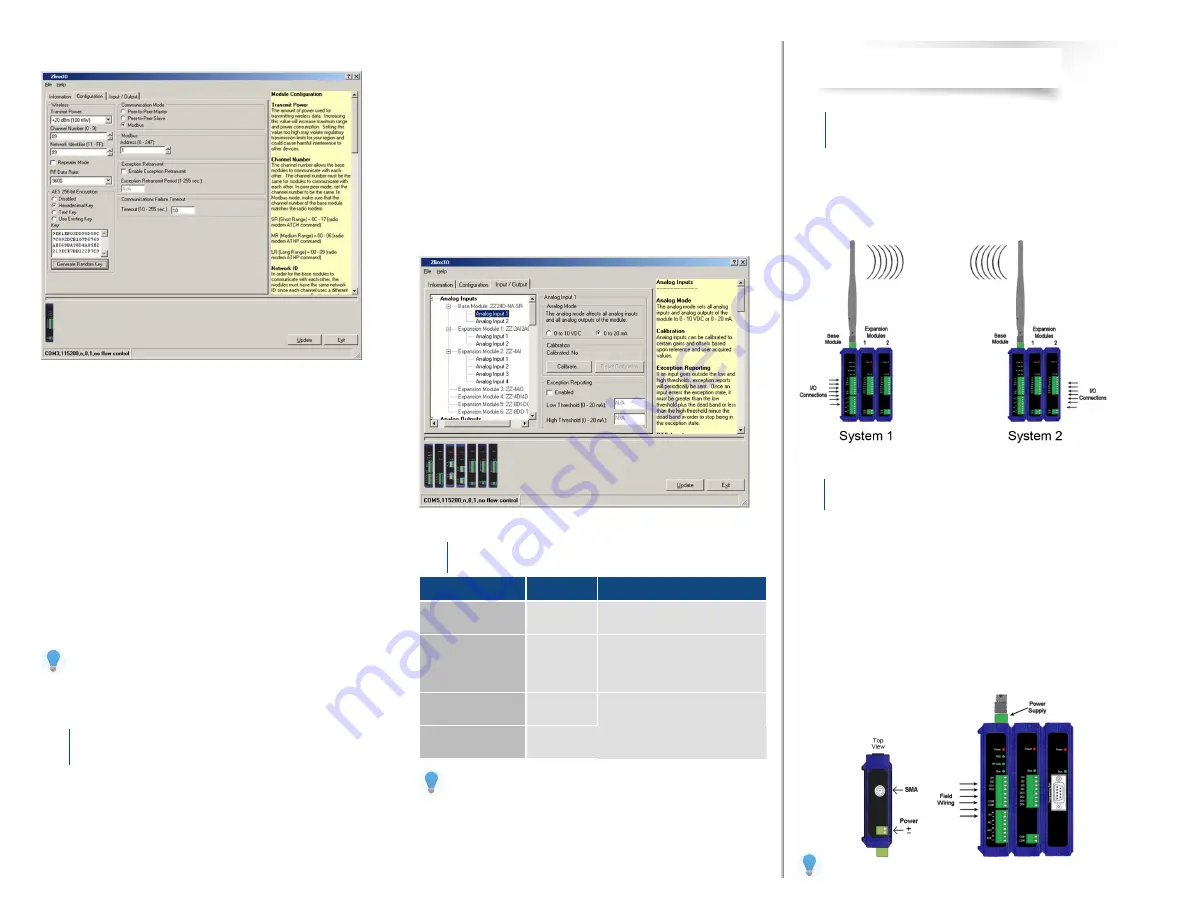
Ensure that two systems are complementary, i.e. the inputs of the modules
in System 1 match the outputs of the corresponding modules in System
2 (see figure below).
Perform an installation site survey to ensure adequate RF coverage and
select a mounting location.
Maximum Ambient Air Temperature for all modules is 80 °C (with the
exception of # ZZ-8DO-R expansion module, which is 65 °C).
Mount and connect together two systems of the base and expansion
modules (expansion modules on the right side of the base).
Ensure that the modules are attached properly.
Plug the Configuration Box into the right side of the system.
Attach the antennas to the base modules.
Connect field wiring to Zlinx I/O terminals.
Refer to the User Manual for power and wattage requirements.


