Select Modules
1
Select a Radio Modem to match the type of Zlinx I/O Base Module (SR
or LR).
Select a Base Module and Expansion Modules based on the type of I/O
needed.
Hardware Installation
2
Install Zlinx
™
I/O Software
4
Insert the Zlinx I/O Manager software CD. Installation should launch
automatically. If not, click Start, Run, [drive]:\ZlinxMgr.exe, where [drive]
is your CD-ROM drive.
Follow the prompts to install the Zlinx I/O Manager.
Start Zlinx
™
I/O Manager
5
Connect a PC serial port (COM1 to 16) to the Configuration Box using a
straight-through serial cable (or USB cable if using a #ZZ-PROG1-USB
module).
Click Start\Programs\B&B Electronics\Zlinx\Zlinx Manager\Zlinx Manager,
then click Zlinx I/O and then Zlinx I/O Configuration. It will auto-search
for attached Zlinx modules on startup. Zlinx I/O will open and display
the Information tab showing model numbers, version numbers of the
attached base and expansion modules.
Make sure that all Base Modules have the same firmware revision.*
Make sure that all Expansion Modules have the same firmware version.*
*This can be verified under the Information tab.
Configure Communication Mode
6
On the Configuration tab:
Select the Modbus Mode to communicate with a Modbus RF modem.
Set the Modbus address to the address number desired for the module
being configured.
MODBUS MODE
Perform an installation site survey to ensure adequate RF coverage and
select a mounting location.
Maximum Ambient Air Temperature for all modules is 80 °C (with the
exception of # ZZ-8DO-R expansion module, which is 65 °C).
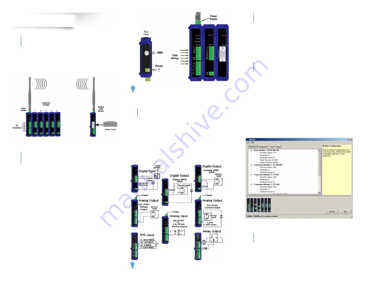
Mount and connect together the base and expansion modules
(Expansion modules snap on the right side of the base unit.)
(Remove and save adhesive sticker covering bus connector.)
Plug the Configuration Box into the right side of the Zlinx I/O system.
Attach antennas to the base module and to the Modbus radio modem.
Mount and connect together Modbus radio modem and Modbus device.
Ensure that modules are attached appropriately.
Connect field wiring to Zlinx I/O terminals.
Connect power to the base module.
Connect power to the Modbus radio modem.
Refer to the User Manual for power and wattage requirements.
Connect Field Wiring
3
Insert the CD into your CD ROM drive. The Zlinx™ Manager Install Wizard
should start. Follow the on-screen instructions to install the software.
If auto run is disabled, locate the
ZlinxMgr.exe
file on the CD-ROM drive
and double click to launch it. The Install Wizard should start. Follow the
on-screen instructions.
Below are samples of Zlinx I/O connecting to both digital and analog
signals.
Refer to the User Manual for input/output voltage and current ratings.


