


13
ACP-2000MB User Manual
Chapter 3
O
peration
3.2
The Rear Panel
The rear panel comes with 3-slot I/O brackets, two reserved 9-pin D-SUB openings
and a motherboard I/O opening.
3.3
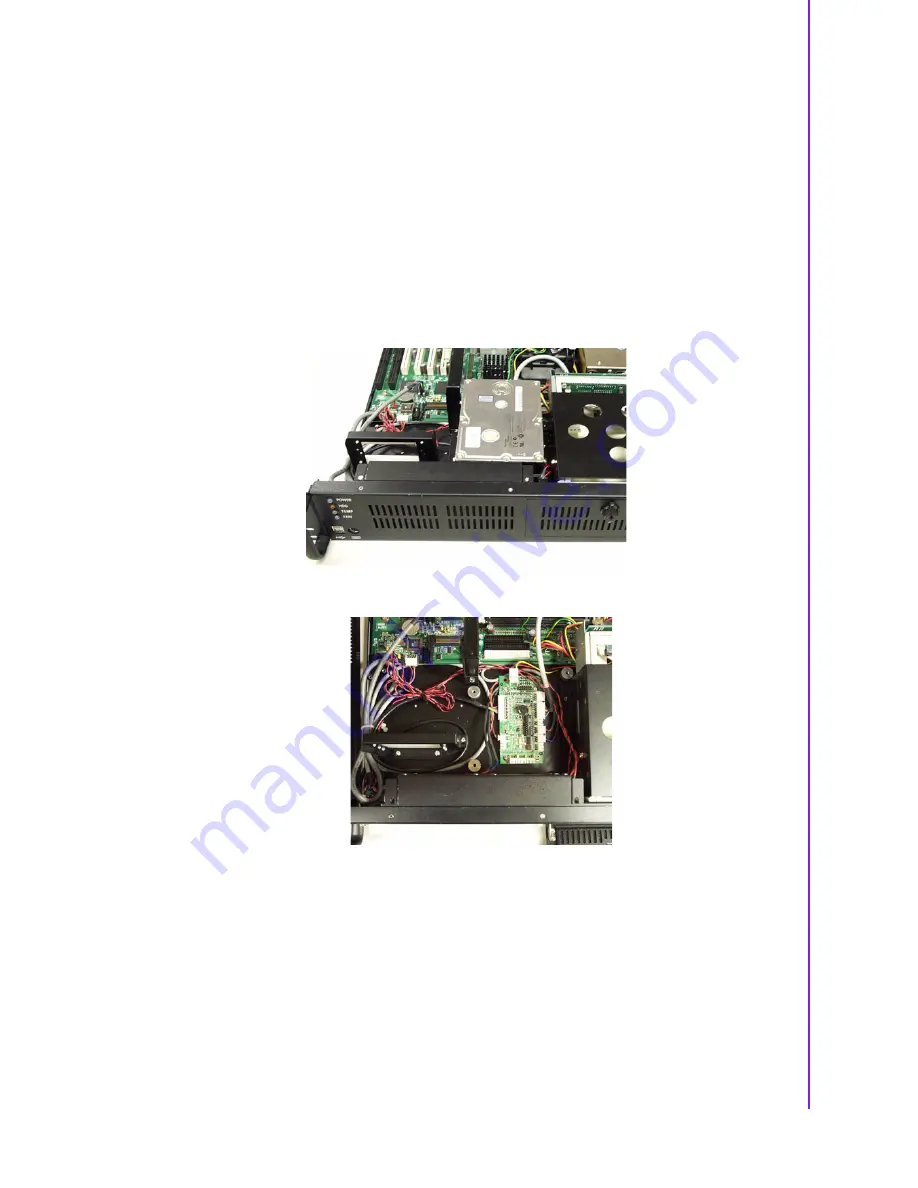
Replacing the Cooling Fans
There are dual cooling fans as shown in Figure 3.1 located inside the chassis. The
cooling fans are low maintenance and provide adequate cooling to the system. If one
of those cooling fans fails, first please release dual cooling fan holder’s two screws,
move away internal 3.5” HDD storage to find the alarm board. Find FAN1 and FAN2
connectors on alarm board, pull out the power wires of the failed cooling fan from the
alarm board. Replace failed cooling fan with a good one. Please refer to Figure 3.2.
Figure 3.1 Dual cooling fans
Figure 3.2 Cooling fan maintenance
Summary of Contents for ACP-2000MB
Page 1: ...User Manual ACP 2000MB 2U 19 Rackmount Chassis for ATX Motherboard...
Page 12: ...ACP 2000MB User Manual 4 1 5 Dimension Diagram Figure 1 1 Dimension diagram unit mm inch...
Page 18: ...ACP 2000MB User Manual 10...
Page 30: ...ACP 2000MB User Manual 22...
Page 31: ...Appendix A A Exploded Diagram...
Page 32: ...ACP 2000MB User Manual 24 A 1 Exploded Diagram...
Page 33: ...Appendix B B Motherboard Options...
Page 35: ...27 ACP 2000MB User Manual Appendix B Motherboard Options...


