23
Chapter 2 Installation
involves one jumper and running the control software (refer to Appendix
A).
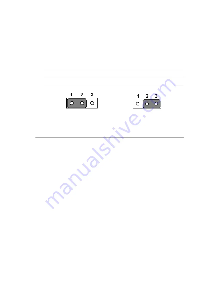
2.22.1 Watchdog timer action (JP5)
When the watchdog timer activates (CPU processing has come to a halt),
it can reset the system or generate an interrupt on IRQ11. This can be set
via setting JP5 as shown below:
2.23 USB connectors (CN20, CN28)
The PCM-9575 board provides up to four USB (Universal Serial Bus)
ports, with USB3 and USB4 optional. This gives complete Plug and Play,
and hot attach/detach for up to 127 external devices. The USB interfaces
comply with USB specification Rev. 1.1, and are fuse protected.
The USB interface is accessed through two 5 x 2-pin flat-cable connec-
tors, CN20 (USB1, 2); and CN28 (USB3, 4). You will need an adapter
cable if you use a standard USB connector. The adapter cable has a 5 x 2-
pin connector on one end and a USB connector on the other.
The USB interfaces can be disabled in the system BIOS setup.
Table 2.6: Watchdog timer action (JP5)
*System reset
IRQ 11
* default setting
Summary of Contents for 100/10
Page 1: ...i PCM 9575 EBX VIA Eden Ezra SBC with CPU LCD Ethernet Audio PCI and PC 104 Plus Users Manual...
Page 4: ...PCM 9575 User s Manual iv...
Page 10: ...x...
Page 16: ...PCM 9575 User s Manual 6 1 4 Board layout dimensions Figure 1 1 Board layout dimensions...
Page 20: ...PCM 9575 User s Manual 10 2 3 Locating jumpers Figure 2 1 Jumper locations...
Page 21: ...11 Chapter 2 Installation 2 4 Locating Connectors Figure 2 2 Connectors component side...
Page 34: ...PCM 9575 User s Manual 24...
Page 41: ...31 Chapter 3 Software Configuration Note For Ethernet installation please see Chapter 7...
Page 42: ...PCM 9575 User s Manual 32...
Page 63: ...53 Chapter 5 PCI SVGA Setup Step 2 Select Adapter then Change...
Page 68: ...PCM 9575 User s Manual 58 Step 2 Choose the Settings tab and press the Display Type button...
Page 69: ...59 Chapter 5 PCI SVGA Setup Step 3 Press the Change button...
Page 73: ...63 Chapter 5 PCI SVGA Setup Step 2 Choose the Video Controller VGA Compatible button...
Page 74: ...PCM 9575 User s Manual 64 Step 3 Choose the Drive button press Update Driver button...
Page 78: ...PCM 9575 User s Manual 68 Step 2 Choose Hardware and Device Manager press OK button...
Page 79: ...69 Chapter 5 PCI SVGA Setup Step 3 Choose Video Controller VGA Compatible press OK but ton...
Page 84: ...PCM 9575 User s Manual 74...
Page 101: ...91 Chapter 6 Audio Setup Step 8 Press Next button Step 9 Press Finish to reboot...
Page 102: ...PCM 9575 User s Manual 92...
Page 108: ...PCM 9575 User s Manual 98 7 2 3 Installation for Windows 2000 Step 1 Open Device Manager...
Page 109: ...99 Chapter 7 PCI Bus Ethernet Interface Step 2...
Page 110: ...PCM 9575 User s Manual 100 Step 3 Step 4...
Page 111: ...101 Chapter 7 PCI Bus Ethernet Interface Step 5 Step 6...
Page 112: ...PCM 9575 User s Manual 102 Step 7 Step 8...
Page 114: ...PCM 9575 User s Manual 104 b Click Next Step 3 a Click Select from list...
Page 116: ...PCM 9575 User s Manual 106 Step 6 Check the highlighted item and click OK...
Page 120: ...PCM 9575 User s Manual 110...
Page 124: ...TPC 642 User s Manual 114...
Page 127: ...117 Appx B Figure B 1 PC 104 module mounting diagram...
Page 128: ...TPC 642 User s Manual 118 Figure B 2 PC 104 module dimensions mm 0 1...
Page 150: ...PCA 6183 User s Manual 140...
Page 155: ...145 Appx E E Optional Extras for the PCM 9575 Appendix...
Page 158: ...PCM 9575 User s Manual 148...
Page 159: ...149 Appx F F Mechanical Drawings Appendix...
Page 161: ...151 Appx F Figure F 2 PCM 9575 Mechanical Drawing component side...
Page 162: ...PCM 9575 User s Manual 152 Figure F 3 PCM 9575 Mechanical Drawing solder side...


