


BC-N4 Glycol Chiller
Page: 25
ADVANTAGE ENGINEERING, INC.
525 East Stop 18 Road Greenwood, Indiana 46142
317-887-0729 Fax: 317-881-1277
Service Department Fax: 317-885-8683
Email: [email protected]
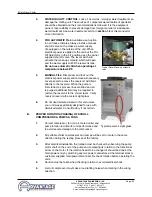
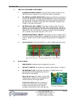
f.
If the motor shaft is phased correctly (shaft turns in a clockwise
direction), continue with step C. If the motor shaft is NOT phased
correctly (shaft turns in a counter-clockwise direction), correct as outlined
in step 2.
2.
If the unit is phased incorrectly, the operator must:
a.
Disengage the electrical power supply to the unit at the unit’s disconnect
switch. Follow all facility proper lock-out tag-out procedures before
proceeding.
b.
Once the electrical power supply is disengaged the operator can change
rotation by switching any two power conductors at the terminal block or
the customer supplied main power disconnect.
C.
PROCESS FLOW ADJUSTMENTS
1.
The operator must determine and set proper water flow rate for the most efficient
and trouble free operation.
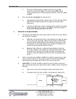
a.
Water flow rate through the process is determined by the pressure losses
in the process loop. Generally, higher flow rates result in turbulent flow
achieving maximum temperature control and lower maintenance. Since
the evaporator in most liquid chillers is flow sensitive, the efficiency of
operation is directly related to the flow of liquid.
b.
Maximum chiller efficiency is obtained at approximately 2.4 gpm per
ton of rated capacity. Low liquid flow can reduce efficiency and in some
cases allow ice to develop in the evaporator which can damage the
evaporator. Excessive liquid flow will trip the motor overload protection
circuit.
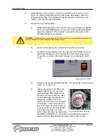
2.
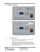
Switch on the illuminated ON/OFF SWITCH to activate the process pump. Wait
a few moments to allow air to be purge from system. Observe the COOLANT
pressure gauge for steady readout. Check unit for low and high flow..
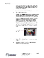
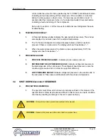
3.
LOW FLOW: If a low flow condition is present, be sure all process valves are
open. If all process valves are open and a low flow conditions exists, consider the
following:
a.
Low flow can cause the low refrigerant pressure limit switch to trip.
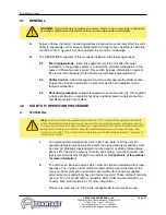
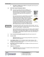
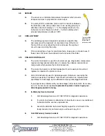
b.
To operate under a low flow condition, it is necessary to install a flow
Typical low flow by-pass loop
Summary of Contents for BC-N4 Series
Page 2: ......
Page 6: ...Page 6 THIS PAGE INTENTIONALLY BLANK ...
Page 20: ...Page 20 THIS PAGE INTENTIONALLY BLANK ...
Page 32: ...Page 32 THIS PAGE INTENTIONALLY BLANK ...
Page 48: ...Page 48 THIS PAGE INTENTIONALLY BLANK ...
Page 54: ...Page 54 THIS PAGE INTENTIONALLY BLANK ...
Page 62: ...Page 62 THIS PAGE INTENTIONALLY BLANK ...
Page 63: ...END 2016 ADVANTAGE ENGINEERING INC RE 09 27 2016 ...
Page 64: ......