background image

 3


Thank you for your purchase of the Advance Radio Air Safe Sequencer .


Air Safe was designed with Giant Scale Models in mind and combines a high quality 


200 psi pressure sensor, a fail safe air monitoring system, a 6 channel Gear sequencer 
with a built in daylight OLED screen and joystick programming.    


In addition, if you are using the Smooth Flite 26 system then you can connect Air Safe to 
the Smooth Flite to add fail safe pressure monitoring to the Smooth Flite main Gear se-
quencer.  


LETS GET STARTED —


in this guide we will show you how to get the most out of the Air 

Safe system. Please take the time to read and understand this guide before installation.


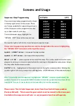
Joystick Control—


Air Safe comes with a built in daylight OLED 

and 5 way joystick.  


Joystick  

↑ 

UP Arrow 


moves up between menu items.


Joystick  

↓ 

DOWN Arrow 


moves down between menu items.


Joystick   


RIGHT


 Arrow 


Increases a value.


Joystick   


LEFT  Arrow 


Decreases a value.


Joystick   PRESS 


Selects and item or new page.


Joystick   PRESS on the word 

RETURN

” 

(at the top of the screen)

 will return you to a previous  

page.


WARNING—Air Safe will power air valves, servos (for gear doors) and linear actuated 
electric retracts i.e. retracts that connect with a servo lead. It is  not designed to directly 
power electric DC motor retracts. 


MULTI CHANNEL USAGE—Air Safe offers up to 6 channels of gear and door sequencing. 
In most cases with air systems 2 or 3 output channels are all that are required for most 
retract setups.  However, If you use a large number of output channels to power servos 
or linear retracts YOU MUST PROVIDE ENOUGH INPUT POWER TO OPERATE THEM.  


DUAL POWER INPUTS—Air Safe has 2 power inputs for larger power setups. The gear 
channel input will provide power and a second input specifically for additional power 
connection. For high power setups connect both the gear channel and the additional 
battery connector to the receiver or Power Expander.  DON

T connect a second battery 

unless the second battery is the same voltage and type as the receiver battery.


Summary of Contents for Air Safe

Page 1: ...Air Safe Failsafe Gear Sequencer User Guide ...

Page 2: ... 3 Features 4 Air Safe Start up Screen 5 Run Mode Screen 7 Programming Main Menu Screen 8 Fail Safe Screen 6 Sequencer Screen 7 Sequencer Outputs 1 6 and Programming 7 8 Sequencer Step Programming 9 Air Safe with Smooth Flite 26 10 Important Sequencer Rules 10 11 Warranty 12 ...

Page 3: ...reases a value Joystick PRESS Selects and item or new page Joystick PRESS on the word RETURN at the top of the screen will return you to a previous page WARNING Air Safe will power air valves servos for gear doors and linear actuated electric retracts i e retracts that connect with a servo lead It is not designed to directly power electric DC motor retracts MULTI CHANNEL USAGE Air Safe offers up t...

Page 4: ...age range can be from 6volts to 8 4volts 6 channel sequencer with PWM outputs to run air valves servos or linear retracts Easy to see daylight OLED screen for setup and pressure monitoring 5 way joystick for easy programmability servo normal reverse on all channels end point setting on all channels Dual power inputs for larger setups ARXL protocol output to connect to any Advanced Radio ARXL devic...

Page 5: ...M PRESSURE 150 0 PSI GEAR POSITION DOWN PROGRAMMING MODE To move to program ming mode press the joystick This will take you to the programming menu Programming Main Menu Screen On the Programming menu use the joystick DOWN Arrow and UP Arrow to move between the different menu items As you move between the different menu items the se lected item will be highlighted with a white background Select FA...

Page 6: ...ure The FS 0 0 PSI will take on the value of the system pressure and the SET FAIL SAFE menu item will change to read CLEAR FAIL SAFE From this point forward if the system pressure SET FAIL SAFE RETURN FS 70 0 PSI LV 70 0 PSI CLEAR FAIL SAFE drops below the Fail Safe pressure a gear down event will be triggered You can clear the Fail Safe pressure highlighting CLEAR FAIL SAFE and pressing the joyst...

Page 7: ...1 SEQUENCER SETUP SEQ OUTPUT 1 6 Joystick RIGHT Arrow Starts a Sequence to the up position Joystick LEFT Arrow Starts a sequence to the down position Joystick PRESS Stops the sequence at the current sequence step Hint The current sequencer position will be shown at the top right of the screen Please Note From the factory the sequencer is programmed with all outputs in the down position for all seq...

Page 8: ...s 1 0 UP POS Highlight this menu item to alter the UP POSITION of an air valve or servo con trolled door DN POS Highlight this menu item to alter the DOWN POSITION of an air valve or servo controlled door NOTE It is important to have the air valve servo position correctly set before you pro gram the sequencer The sequencer assumes the Up and Down positions have been cor rectly set SEQ OUTPUT 1 SPE...

Page 9: ...the selected output Hint To manually test the sequencer highlight the RETURN and press push down the joystick Then use the manual UP DOWN function to test the up and down function of the sequencer You can of course also use the transmitter to test the sequencer Please note The Air Safe Sequencer Arms From Gear Switch Down position Factory Default This means the gear switch must be moved to the dow...

Page 10: ...e next step Example 1 a Slowest Servo Speed set to 5 b Wait To Next Step set to 2 0 seconds c Total step time approx 1 second 2 0 3 0 seconds Example 2 a All servos Speed set 0 0 b Wait To Next Step set to 2 0 seconds c Total step time 0 0 2 0 2 0 seconds In this example it will appear as if the step was missed Example 3 a All servos Speed set 0 0 b Wait To Next Step set to 0 0 seconds c Total ste...

Page 11: ...itch is switched to Gear UP position Step 2 Gear transitions to up position and doors remain open Wait Time 5 0 Seconds for gear to transition Step UP Gear is in UP position and Doors transition to closed Wait Time 1 0 Seconds Gear Doors Gear Doors Gear Doors Gear Doors Wait Time 0 0 Seconds Gear Down To Up Sequence Step wait times are normal Transmitter switch is set to Gear DOWN position Step DO...

Page 12: ...chieve a very high quality and reliable product Our QC process provides for complete system functionality testing followed by rigorous load and stress testing If the unit passes this stress test it is further run and heat soaked at 60 C for a period of 8 hours prior to final testing where it is load tested for a second time If it passes these tests it is then packaged We believe in our processes a...

Reviews: