background image


TM

14

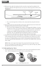
12.  Slide pole #6 into place by inserting it into the sleeve that runs along the underside of the      
   front deck.  Slide pole #6 though this sleeve and connect it with the top portion of the bow rib.   

   See Figure 12.

Figure 12


  a.   Tip:  Access the top portion of the bow rib to connect pole #6 by using the front deck      
   

 zipper.

13.  Once all of the poles have been installed into the kayak, align the front and rear thwarts with   
   the alignment lines printed on the interior floor of the kayak.

  a.   Tip:  The front thwart alignment line is meant as a starting point for inflation.  You may   
   

 find that you want to move it forward or backward to adjust for proper foot bracing  and  


 comfort.  It is recommended that you inflate it at the alignment line for your  first time,     


 and then you can deflate and adjust the thwart as needed to fit your height and         


 preference.  Once you determine the position that best suites you, you can  mark         


 the position  of the front thwart with a permanent marker for future setups.

14.  Attach the seat to the buckles located inside the cockpit area (the cockpit buckles are attached   
   to the underside of the deck of the kayak). There are 4 buckles in the cockpit area, as well as    
   on your seat. The large buckles on your seat attach to the larger buckles located at the front     
   end of the cockpit and the small buckles on your seat attach to the smaller buckles at the rear   
   of the cockpit.
 

   NOTE: 

 Make sure to align the back edge of the seat pad with the back edge of the foam      

   floor. The seat should not be positioned any further back. If you need more leg room, adjust    
   the placement of the front thwart, not the seat.

3.3  Understanding Your Valves

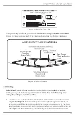
1.   The AirFusion kayak uses the standard Boston valves and the Advanced Elements Twistlok    
   Valve.  The following figures have details on how to operate these valves.


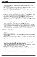
Figure 1. Inflate/Deflate Boston Valve


Deflate 

Inflate

Summary of Contents for AirFusion AE1040-Y

Page 1: ...ANUAL CAREFULLY BEFORE PROCEEDING AFTER READING THIS MANUAL SAVE THESE INSTRUCTIONS FOR FUTURE REFERENCE AirFusion Inflatable Kayak Owner s Manual MODEL AE1040 Y 1 PERSON KAYAK ADVANCED ELEMENTS INC 2...

Page 2: ...ts bow slices through water like a knife and rivals the tracking of hard shell kayaks The stern acts as a skeg increasing the tracking performance The Lagoon kayaks are durable and lightweight They ha...

Page 3: ...mbly 7 3 2 Set Up 9 3 3 Understanding Your Valves 14 3 4 Inflating 15 3 5 Deflation and Break Down 16 3 6 Folding 17 4 Guidelines for Usage 18 5 Proper Care and Storage 18 6 Repairs 19 6 1 Repairing S...

Page 4: ...CHECK YOUR EQUIPMENT PRIOR TO EACH USE FOR SIGNS OF WEAR OR FAILURE NEVER PADDLE ALONE DO NOT PADDLE IN FLOOD CONDITIONS BE AWARE OF APPROPRIATE RIVER WATER LEVELS TIDAL CHANGES DANGEROUS CURRENTS WE...

Page 5: ...damage CAUTION Indicates a potentially hazardous situation which if not avoided may result in property damage CAUTION Used without the safety alert symbol indicates a potentially hazardous situation...

Page 6: ...TANDARDS OF EFFECT ON THE DATE OF CERTIFICATION NATIONAL MARINE MANUFACTURES ASSN NOT INTENDED FOR MECHANICAL PROPULSION 2010 AirFusion Kayak Capacity Label WARNING Do not exceed the certified maximum...

Page 7: ...omponents will be with the kayak but not installed these include 1 Front and rear inflatable thwarts 1 each 2 Foam Floor x 1 3 Seat x 1 4 Pole 1 x 1 5 Pole 2 x 1 6 Locking Sleeve 3 x 1 7 Pole 4 x 2 8...

Page 8: ...ace using the Velcro loops at the bottom position 2 With the main tube chambers deflated insert each set into the outer cover making sure the valves are facing inwards Make sure the large Velcro close...

Page 9: ...ck end the portion that will be directly behind your seat 2 Assemble the frame poles by interlocking the shock corded ends together 3 Install the Foam Floor The Foam floor should be placed with the wi...

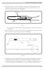
Page 10: ...Figure 5 Figure 5 a Tip Connect pole 1 with the Bow Rib through the zipper on the deck at the front end of the kayak 6 Insert pole 2 into the sleeve on the bottom of the rear thwart leave deflated mak...

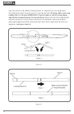
Page 11: ...the kayak 8 Slide Locking Sleeve 3 over the end of pole 2 at the cockpit position making sure the hole for the snap button is facing the free end of pole 2 See Figure 8 Figure 8 9 Connect poles 1 and...

Page 12: ...leeve 3 into place IMMEDIATLY to prevent poles 1 and 2 from springing upwards and causing any injury to you or the kayak Align and secure the completed pole assembly using the two Velcro loops on the...

Page 13: ...guide loop that is located along the side of the kayak at the stern of the boat a Tip Access the rear guide loop through the rear deck zipper After positioning poles 4 and 5 connect the two ends maki...

Page 14: ...d preference Once you determine the position that best suites you you can mark the position of the front thwart with a permanent marker for future setups 14 Attach the seat to the buckles located insi...

Page 15: ...Do not over inflate 1 Locate the valves for the two bottom side chambers Make sure the valve body is screwed in tightly See Figure 1 Remove small cap and use the appropriate pump nozzle If you own an...

Page 16: ...yellow Velcro loop located at the rear of the cockpit on the underside of the kayak deck to store the Rear Thwart inflation hose The inflation hose for the Front Thwart can be placed on top of the le...

Page 17: ...2 Fold in half down the center lengthwise 3 Fold the bow inward at the end point of the Bow Rib You should be able to feel the end of the Bow Rib through the outer cover 4 Fold over at the tip of the...

Page 18: ...blade close to the kayak and the paddle almost vertical Pull with your lower hand and push with your upper hand To reduce the amount of swaying at the front of the kayak ease off on the force of your...

Page 19: ...n the Velcro squares on the outer side of the tube sleeves with the Velcro squares of the inner side walls of the outer skin Additionally be sure to connect the large Velcro squares at each end of the...

Page 20: ...ar where a leak may be take a clean rag with soapy water and begin rub bing the tube If a hole is present bubbles will continually form Repair using repair kit If it is a very small pinhole a dab of t...

Page 21: ...S It is alway a good idea to keep nots of your paddling experiences Your notes can serve as a reminder of what to look out for as well as what gear to bring along and what conditions are like DATE TIM...

Page 22: ...TM 22 NOTES...

Page 23: ...AirFusion Inflatable Kayak Owner s Manual 23 NOTES...

Page 24: ...NOTES...

Page 25: ...knowledge TM P O Box 5128 Concord CA 94524 Signature_________________________________________________________________________________ FIRST ASSIGNMENT FOR VALUE RECEIVED in the amount of ____________...

Page 26: ...on relates meets the essential health and safety requirements and is in conformity with the relevant EU Directives listed below General Product Safety Directive using the relevant section of the follo...

Page 27: ...CH EXTEND BEYOND THE DESCRIPTION OF THE FACE HEREOF AD VANCED ELEMENTS SHALL NOT BE HELD LIABLE FOR INCIDENTAL AND CONSEQUENTIAL DAMAGES THIS WARRANTY IS INCLUSIVE IN LIEU OF ALL OTHER WARRANTIES This...

Page 28: ...like a catalog of our latest products please visit our website at www advancedelements com or call Toll Free 866 262 9076 PLEASE COMPLETE THE OTHER SIDE OF THIS WARRANTY REGISTRATION CARD AND RETURN T...

Reviews: