Advanced Electronics MX-5101 User Manual Download Page 34


34 

When the activating test key is removed from the call point or the smoke clears from the detector chamber, the 
panel will automatically reset and clear the test condition. 

As an alternative to scrolling, a specific zone number can be entered by using the 


button to


move to the zone 

number column, and then typing in the required number, followed by the 

 button. 

If several consecutive zones are to be tested, an alternative to selecting them all individually is to specify a 
range of zones as follows: -  

Move to the zone number column and highlighting the first zone to test, then 

Press the 

 button 

– the display will then ask for the last zone to be tested. 

Individual zones can then be toggled in or out of test by pressing the 

 button. 

To leave the Zone Test menu, press the 

‘Esc’ 

button.  If there are still any zones in a test condition a pop-up 

window with the following options: - 


  FINISHED TEST            

.


  KEEP ZONES IN TEST 


Selecting the FINISHED TEST option will cancel all zone tests. The Test LED will then extinguish. 

Alternatively, it is possible to leave the Zone Test Function with one or more Zones still in Test by selecting the 
KEEP ZONES IN TEST option. This will enable the inspection or use of other menu functions and return the 
display to the normal operating mode.  The Test LED will stay illuminated if this option is selected. 

3.13.2 Test - Display 

The Test Display option checks the operation of all the Indicators and the Graphic Display. All of the Indicators 
are turned on and the entire display is shown in reverse. 

During this test, it is possible to test the operation of the 

,

,

,

,

 and 

0-9

 buttons. When a button is 

pressed, it is indicated on the display. For example: 


LCD & KEY TEST 


Press the 

‘Esc’ 

button


to return to the Test Menu. If no button is pressed for 1-minute, the display will 

automatically revert to the normal operating display. 

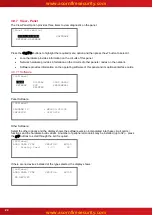
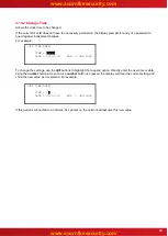
3.13.3 Test - Buzzer 

 [Test Menu]              User 1 Node  1 
 
   ZONES   DISPLAY   

BUZZER

   PRINTER 

   OUTPUTS 


When the Test Buzzer option is selected, the internal buzzer will sound for about five seconds. 

www.acornfiresecurity.com

www.acornfiresecurity.com

Summary of Contents for MX-5101

Page 1: ...Fire Alarm Panels User Manual The operation and functions described in this manual are available from Software Version 5000 050 04 onwards www acornfiresecurity com www acornfiresecurity com...

Page 2: ...2 This page is intentionally blank www acornfiresecurity com www acornfiresecurity com...

Page 3: ...EMENT CONDITION 15 3 4 1 Disabled Inputs 15 3 4 2 Disabled Outputs 16 3 5 ALARM CONDITION 16 3 6 SUPERVISORY CONDITION 17 3 7 MULTIPLE CONDITIONS 17 3 8 MENU FUNCTIONS 17 3 8 1 Using the Buttons to Na...

Page 4: ...0 3 12 DELAYS 31 3 12 1 Turn Off Delay Mode 31 3 12 2 Turn On Delay Mode 31 3 12 2 1 Extend Delays 32 3 12 2 2 Holiday Inhibit 32 3 13 TESTING 33 3 13 1 Test Zones 33 3 13 2 Test Display 34 3 13 3 Tes...

Page 5: ...uts Dependency on more than one alarm signal Fault Signals from Points Disablement of Points Alarm Counter Test Condition Standardised Input Output EN54 4 1997 A1 2002 A2 2006 Power supply equipment f...

Page 6: ...ommissioning Manual Document No 680 165 for details of how to install and program the panel All panel models are available in a range of enclosure sizes and with a range of alternative optional featur...

Page 7: ...E FAULT FIRE ROUTING ACTIVATED FIRE ROUTING FAULT FIRE ROUTING DISABLED PRE ALARM SOUNDER SILENCED SOUNDER FAULT Graphical Liquid Crystal Display Navigation Keys Zone LED Indicators Optional Number Ke...

Page 8: ...Indicates that the circuit to fire extinguishing or other fire protection equipment has been activated or that the fire protection equipment itself has been activated Sounder Silenced Yellow Indicates...

Page 9: ...l 2 Access Resound Press to re activate the sounders Only available with Level 2 Access Evacuate Press to initiate a manual evacuation and sound the alarms Only available with Level 2 Access LED Test...

Page 10: ...Maintenance Engineer Special Tools required A Level 1 Untrained User can view the current operational condition of the system and may MUTE the internal buzzer NOTE Depending on the configuration setti...

Page 11: ...mber is entered an asterisk is shown on the display For example CONTROLS DISABLED Please Enter Your Password If the password is correct the Level 2 Menu options will be shown If the password is incorr...

Page 12: ...cation Text for First Zone Location Text and Type of Device 2 Zones in Fire Last Zone 0005 BASEMENT EAST No of Zones in Fire Last Zone Zone Description for Last Zone Press the MUTE button to silence t...

Page 13: ...Delays The Investigation Delay Function can be disabled or enabled as required by EN54 2 Refer to Section 3 12 If the Investigation Delay Function Stage 1 Stage 2 Investigation Delay is enabled a fire...

Page 14: ...the current time and date and service centre telephone number along with the indication of the fault FOR SERVICE CALL 01234 567890 LEVEL 2 16 05 04 MAR 2008 Panel access level Service Call Number and...

Page 15: ...then press the button to view further information 3 4 1 Disabled Inputs The display presents a list of all of the zones in a disabled condition with the first disablement highlighted For example 2 Zo...

Page 16: ...formation including type value and state etc Outputs in Zone 0100 More Mode Type Disabled SOUNDER Disabled SOUNDER Disabled SOUNDER Disabled SOUNDER Press the buttons to scroll through the list of ind...

Page 17: ...ondition to occur however is shown at the top of the display An example of the display is shown below ZONE 0011 SUPERVISORY PLANT ROOM SPRINKLER SHUT OFF INPUT MON Location Text for First Zone Locatio...

Page 18: ...d disablement group ENABLE Zone Inputs Enable a complete zone or an individual input Outputs Enable sounder outputs or other devices Groups Enable a user defined disablement group Remote Permits remot...

Page 19: ...to the normal operating display Press the Menu button to return directly to the Level 2 Menu display previously shown 3 8 1 2 Selecting Individual Zone Numbers When the display is showing a list of Zo...

Page 20: ...in a Fault condition The operation of the panel and the information that can be shown is identical to the views available from the main operating display Refer to Section 3 3 for further information...

Page 21: ...onal condition for all Outputs Outputs More Zone Location 0002 Reception 0003 Ground Floor 0013 First Floor Corridor 0014 First Floor Press the buttons to highlight the required zone and then press th...

Page 22: ...optional interface cards 3 9 7 1 Software Software PANEL DISPLAY LOOP CARDS NETWORK PSU PERIPHERAL PRINTER Panel Software Software PROGRAM ID MX5000 050 04 CHECKSUM 92879016 Other Software Select the...

Page 23: ...Earth Volts 0V 30V 2 5V 14 5V 6 Normal Too High Too Low System Volts 19V 30V 28 0V Normal Aux Load 0mA 500mA 5 Normal Too High 1 st Loop Load 7 0mA 500mA 5 Normal Open Circuit Too High Short Circuit...

Page 24: ...buttons to highlight the required menu option and then press the button to select it The display then shows the appropriate list of events 3 9 8 1 Event Log The display will always show the most recen...

Page 25: ...502 Pressing 0 allows the stored network status information to be cleared 3 9 10 View Warnings This Option can be used to obtain information about warning conditions on the panel A warning condition...

Page 26: ...croll through the available zones or key in a specific zone number To disable the entire zone move over to the Mode column and highlight the existing mode Press the button and a pop up window appears...

Page 27: ...TS FIRE PROTECTION OUTPUTS FAULT ROUTING OUTPUTS ALL OTHER RELAY OUTPUTS ONLY SELECTED OUTPUTS PAGERS 3 10 2 1 All Sounder Outputs Press the buttons to scroll through and highlight the ALL SOUNDERS Op...

Page 28: ...able Menu 3 10 2 9 Only Selected Outputs Allows selection of a single output 3 10 3 Disable Controls Disabling Controls will cancel Level 2 access and return the panel to Level 1 operation If the pane...

Page 29: ...Disablement Groups are a means of disabling enabling custom groups of devices The commands are command across the network of panels and can be invoked from any panel The installer will have configured...

Page 30: ...bled The individual outputs within the zone can then be enabled The display format is virtually identical to the equivalent Disable Menu 3 11 3 Enable Groups This option allows the re enabling of User...

Page 31: ...ion delays in operation If the investigation delays are in operation then the Delayed LED Indicator is illuminated When the investigation delays are turned off the Delayed LED Indicator is turned off...

Page 32: ...oliday periods On selection the display shows Inhibit Delay End Date TIME 15 49 DATE 02 07 08 WED 02 JUL 2008 Press the buttons to select the time date fields Enter the required time and date using th...

Page 33: ...ssioning to define which of the sounders are activated during a test The display then shows a list of the available Zones and their current test status For example 0 Zones in Test Zone Test State Loca...

Page 34: ...TEST option will cancel all zone tests The Test LED will then extinguish Alternatively it is possible to leave the Zone Test Function with one or more Zones still in Test by selecting the KEEP ZONES...

Page 35: ...OM 0100 MAIN RECEPTION Press the buttons to scroll and highlight the required zone or key in the required zone number and then press the button to show the output devices in that zone For example Outp...

Page 36: ...to confirm If the current User ID does not have the necessary permission the display prompts for entry of a password to guard against inadvertent changes Enter the password as normal The display then...

Page 37: ...printed includes Device Text Zone Number Loop and address current status and analogue value 3 14 1 4 Print Outputs To print information on any output highlight the Outputs option and press the button...

Page 38: ...number keys to change the zone number as required Press the key to start printing The printout will show the location and state of all input and output points in a disabled condition for the zones se...

Page 39: ...09 To change the settings use the buttons to highlight the required option Directly enter the new time or date using the number buttons As soon as a number button is pressed the display will clear the...

Page 40: ...40 This page is intentionally blank www acornfiresecurity com www acornfiresecurity com...

Page 41: ...41 This page is intentionally blank www acornfiresecurity com www acornfiresecurity com...

Page 42: ...42 USER NOTES www acornfiresecurity com www acornfiresecurity com...

Page 43: ...www acornfiresecurity com www acornfiresecurity com...

Reviews: