


ZDW103 Instructions, Release 1.1
P/D 102406
HomePro
by ADVANCED CONTROL TECHNOLOGIES, INC.
0703-01
2
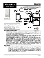
Proper Single Gang Installation
Using ZDW103’s standard full heat-sink (all tabs), the connected incandescent lamp load shall not exceed 800W.
If a tab is removed from one side of the ZDW103 unit, the connected incandescent lamp load must not exceed 700W.
If both tabs are removed from the ZDW103 unit, the connected incandescent lamp load must not exceed 600W.
Proper Dual Gang Installation
The connected incandescent lamp load must not exceed 600W for each of the two ZDW103 units.
Proper Triple Gang Installation
The connected incandescent lamp load must not exceed 500W for each of the two ZDW103 units.
Air Gap Switch
The ZDW103 has an air gap switch on the face (lower left), that when pulled out, completely removes the power
available to the load (more so than simply turning the dimmer off). This enables the lamps that are controlled by
the device to be changed with minimal danger of electrical shock. The air gap switch must be pushed all the way
back in for the dimmer to operate the lamps again.
Thermal SW (Software) Fuse:
This product is equipped with a thermal software fuse. The thermal software fuse will trigger when the controlled
wattage exceeds 800 watts. The Load must be reduced to 800W or less to prevent this condition from occurring.
What will happen if this condition occurs?
If the thermal software fuse is activated, the output power will be reduced to 50% to prevent damage to the dimmer.
The LED on the front of the ZDW103 will blink at a 2.5 second rate. If the unit has not cooled down after 5 minutes,
the output power will be reduced to 25%. The LED will then blink at a 1 second rate. If another five minutes passes
and the temperature is still too high, the output power will be reduced to 10%. The LED will then blink at a very
fast rate. Reduce the total wattage to avoid damage.
Local and Remote DIM/BRIGHT Control of the load will not be available while in this state. Local DIM/BRIGHT
control of the affected ZDW103 from associated Z-Wave dimmers/devices will not be available while in this state.
ON/OFF control will be available locally, remotely or from associated dimmers/devices. If the safe temperature
has not been reached, the maximum level set by the SW Fuse will be retained when the ZDW103 is turned OFF
and then back ON.
If at any time the safe operation temperature is achieved, normal operation will return and the LED will stop blinking,
but the output will remain at the power that allowed the dimmer to cool. The dimmer will allow maximum output
power again.
Remember to reduce the load on the output to 800W or lower to prevent the software fuse from triggering again.
INCLUDING ZDW103 TO THE NETWORK
STEP 2.
. Prepare the Controller to include a unit to the network (Refer to controller instructions).
STEP 3.
The ZDW103 must be in its permanently installed location.
Tap either the top or bottom of the
switch paddle on the ZDW103 once.
STEP 4.
You should see an indication on your Controller that the “device was included” in the network.
BASIC OPERATION
Local Control
From the front paddle switch, the ZDW103 allows the user to do the following:
•
Turn ON or OFF, DIM or BRIGHTEN, the load attached.
•
Include or exclude the module from the Z-Wave network.
•
Configure to Control Shades or Window Coverings via Z-Wave network.
•
Control other Z-Wave enabled devices.
Also, when a controller prompts you to “Send Node ID” or to “Press Button on Unit”, quickly tap the top or bottom
of the switch once to satisfy those instructions.