


4
617108148PF2-13D
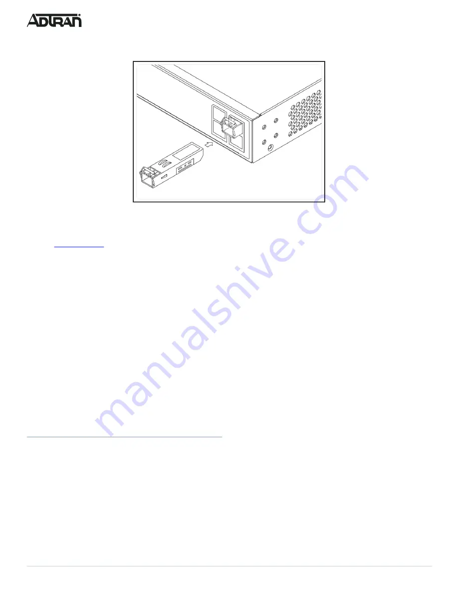
2. Press firmly to ensure that the module seats properly into the connector.
Figure 7. Installing an SFP+ Module into an SFP+ Port
g
NOTE
This product is intended for use with a Class 1 Laser module that complies with FDA 21 CFR 1040.10, 1040.11 and IEC 60825-1. For
continued compliance with the above standards, only approved Class 1 Laser modules from an ADTRAN approved vendor list (located
online at
) should be installed in this product. ADTRAN cannot certify system integrity with other laser modules.
Initially Configuring the Switch
The Switch can be configured by two methods:
■
Web based Graphical User Interface (GUI)
■
Command Line Interface (CLI)
Initial Switch Configuration Using a Web Browser
After powering up the switch for the first time, you can perform the initial switch configuration using a web browser.
To begin with the initial configuration stage, you need to reconfigure your PC’s IP address and subnet mask to make sure the PC can
communicate with the switch. After changing PC’s IP address (for example, 10.10.10.250), then you can access the web interface of the
switch using the switch’s default IP address as shown below.
g
NOTE
The factory default IP address of the switch is
10.10.10.1
and the subnet mask is
255.255.255.0
. If the switch is connected to a Dynamic
Host Control Protocol (DHCP) server, the server assigns the switch an IP address and the default
10.10.10.1
IP address is not
configured. The DHCP server also assigns your PC the correct IP address to allow a connection on the same subnet as the switch.
Initial Switch Configuration Procedure
To initially configure the switch, complete the following steps.
1. Power up the PC that you will use for the initial configuration. Please make sure the PC has the Ethernet RJ-45 connector to be
connected to the switch via standard Ethernet LAN cable. If the switch is connected to a DHCP server, skip to Step 3.
2. Reconfigure the PC’s IP address and subnet mask as below, so that it can communicate with the switch. For example, the method
to change the PC’s IP address for a PC running Windows® 7/8.x/10 is as follows:
a. Type
network and sharing
into the Search box in the Start Menu.
b. Select
Network and Sharing Center
.
c. Select
Change adapter settings
on the left of PC screen.
g
NOTE
Users can also skip Steps 1-2, by pressing
R
and typing the
ncpa.cpl
command to get to Step 4 directly.


