ADTRAN NetVanta 1560-48-740W Quick Start Manual Download Page 2

2

617108148PF2-13D

Installation Overview

To install the switch, you will need to do the following:

1. Mount the switch
2. Connect AC Power
3. Install SFP+ Modules

Installation Steps

To install the NetVanta 1560-48-740W switch, complete the following steps:

Mount the Switch

The switch can be mounted in a 19-inch rack, or on a desk or shelf.

Mounting in a 19-inch Rack

To mount the switch into a 19-inch rack, complete the following steps.

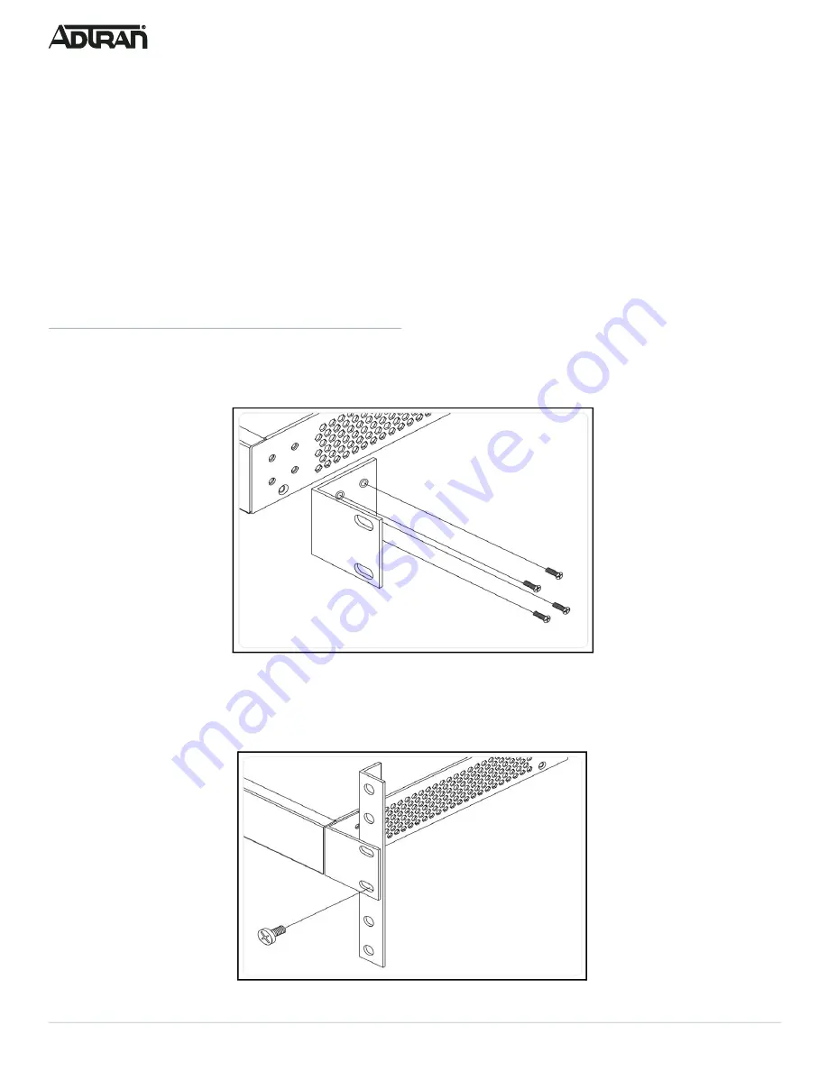
1. Attach the mounting brackets to both sides of the chassis. Insert the provided screws and tighten them with a screwdriver to secure 

the brackets.

Figure 3. Attaching Brackets to the Switch

2. Place the switch on a rack shelf in the rack. Push it in until the oval holes in the brackets align with the mounting holes in the rack 

posts.

3. Secure the brackets to the posts by inserting rack screws and tightening them with an appropriate screwdriver. Rack mount 

brackets are a default accessory with the unit; spare brackets can be ordered through ADTRAN, part number: 1700519F1.

Figure 4. Attaching Brackets to the Rack Post

Summary of Contents for NetVanta 1560-48-740W

Page 1: ...art f WARNING The NetVanta 1560 48 740W is intended for indoor use only Ethernet PoE cables and attached equipment are intended for use within the same building with equipotential bonding and not inte...

Page 2: ...g steps 1 Attach the mounting brackets to both sides of the chassis Insert the provided screws and tighten them with a screwdriver to secure the brackets Figure 3 Attaching Brackets to the Switch 2 Pl...

Page 3: ...top and sides of the unit for sufficient air flow Connect AC Power To connect the AC power cord to the switch complete the following steps 1 Connect the AC power cord to the AC power receptacle on th...

Page 4: ...face of the switch using the switch s default IP address as shown below g NOTE The factory default IP address of the switch is 10 10 10 1 and the subnet mask is 255 255 255 0 If the switch is connecte...

Page 5: ...the two console ports USB RJ45 available in the switch To establish the connection to the console port the following are needed PC with VT100 terminal emulation software Micro USB to USB cable or a DB...

Page 6: ...LED On The port status LEDs are displaying link status network activity and the speed of each port LED Color State Description PoE On The RJ 45 port status LEDs are displaying the PoE powering status...

Page 7: ...faults 7 12 seconds Flashing Green All LEDs are ON Symptoms Possible Causes Suggested Solutions System LED is OFF The switch is not receiving power 1 Check if correct power cord is connected firmly to...

Page 8: ...0 C to 45 C Storage Temperature 40 F to 158 F 40 C to 70 C Relative Humidity 10 to 95 percent non condensing Electrical Power Supply 100 to 240 VAC 50 60 Hz 11A Documentation for ADTRAN Network Solut...

Reviews: