ADTRAN NetVanta 1560-24-740W Quick Start Manual Download Page 3

617108124PF2-13D

3

Mounting on a Desk or Shelf

To mount the switch on a desk or shelf, complete the following steps.

1. Verify that the desk or shelf is sturdy enough to support the switch. 
2. Attach the four adhesive rubber feet to the bottom of the switch.

Figure 5. Attaching the Rubber Feet

f


CAUTION!

Desk, shelf, or wall mounting of the equipment should be such that the amount of air flow required for safe operation of the equipment is not compro

-

mised. Allow 1-inch clearance on the top and sides of the unit for sufficient air flow.
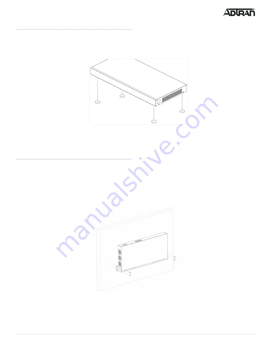
Mounting on a Wall

To mount the switch on a wall, complete the following steps.

1. Using the mounting holes on the bottom of the unit as a template, install the user-supplied screws in the appropriate location on the wall. Be aware 

of the dimensional limitations of the screws. Hang the switch on the screws and ensure that it is securely attached.

f


CAUTION!

The NetVanta 1560-24-740W must be mounted in the face down orientation when wall mounted.

Figure 6. Install Screws in the Wall and Hang the Switch on the Screws

g

     NOTE

The wall mount brackets are not supplied with the unit and must be purchased separately from ADTRAN, part number 1700520F1. 

Summary of Contents for NetVanta 1560-24-740W

Page 1: ...ck mount two brackets and eight screws Quick Start f WARNING The NetVanta 1560 24 740W is intended for indoor use only Ethernet PoE cables and attached equipment are intended for use within the same building with equipotential bonding and not intended to be placed in separate buildings or structures Failure to deploy as described could result in permanent damage from lightning or other electrical ...

Page 2: ...1 Attach the brackets provided in the mounting kit to both sides of the chassis Insert the provided screws and tighten them with a screwdriver to secure the brackets Figure 3 Attaching Brackets to the Switch 2 Place the switch on a rack shelf in the rack Push it in until the oval holes in the brackets align with the mounting holes in the rack posts 3 Secure the brackets to the posts by inserting r...

Page 3: ... and sides of the unit for sufficient air flow Mounting on a Wall To mount the switch on a wall complete the following steps 1 Using the mounting holes on the bottom of the unit as a template install the user supplied screws in the appropriate location on the wall Be aware of the dimensional limitations of the screws Hang the switch on the screws and ensure that it is securely attached f CAUTION T...

Page 4: ...te SFP port 2 Press firmly to ensure that the module seats properly into the connector Figure 8 Installing an SFP Module into an SFP Port g NOTE This product is intended for use with a Class 1 Laser module that complies with FDA 21 CFR 1040 10 1040 11 and IEC 60825 1 For continued compliance with the above standards only approved Class 1 laser modules from an ADTRAN approved vendor list llocated o...

Page 5: ...net Protocol Version 4 TCP IPv4 Then select the Properties button g NOTE Be sure to record all your PC s current IP settings to be able to restore them later Select the radio button Use the following IP address and enter in the IP address for the PC e g any IP address not in use and in between 10 10 10 2 and 10 10 10 254 subnet mask e g 255 255 255 0 Select OK to change the PC s IP address 3 Power...

Page 6: ...larm has been triggered for troubleshooting LINK ACT SPD Mode LED The LINK ACT SPD Mode LED indicates the port status LEDs are displaying in link act speed mode PoE Mode LED The PoE Mode LED indicates the port status LEDs are displaying in PoE mode Port Status LEDs The Port Status LEDs indicate the current status of each port in either Link Act Speed mode or PoE mode By pressing the MODE button fo...

Page 7: ...to a connected device On An abnormal state such as an overload status has been detected in the switch Off The port has no active network cable connected or it is not connected to a PoE powered device Other wise the port may have been disabled through the switch user interface Task Press for System LED Behavior Port Status LED Behavior Change LED Mode 0 2 seconds Solid Green LED status will change ...

Page 8: ...erference received including interference that may cause undesired operation Changes or modifications not expressly approved by ADTRAN could void the user s authority to operate this equipment g NOTE This equipment has been tested and found to comply with the limits for a Class A digital device pursuant to part 15 of the FCC Rules These limits are designed to provide reasonable protection against ...

Reviews: