


617101561F1-13A
7
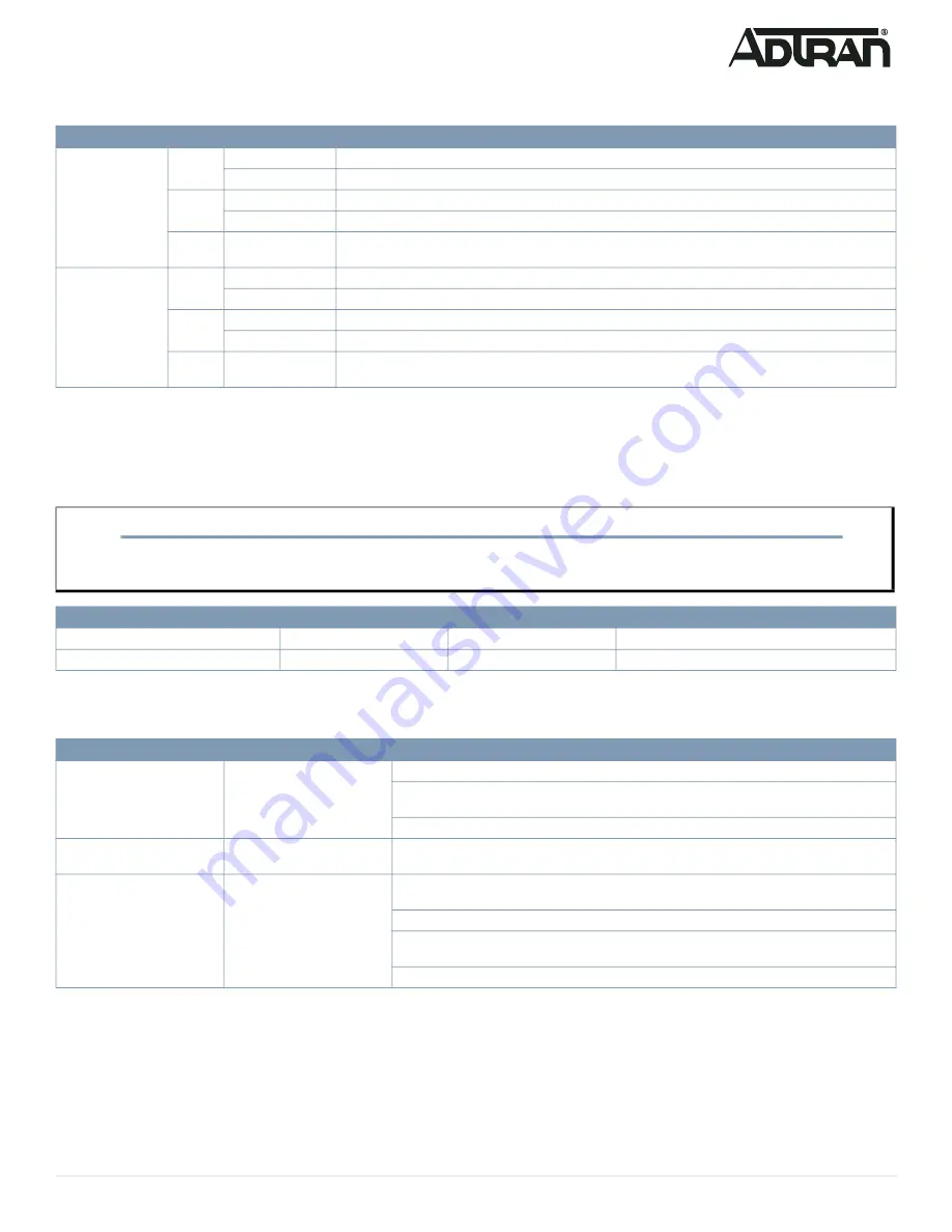
Port Status LEDs
The Port Status LEDs indicate the current status of each port.
Resetting the Switch
By pressing the
RESET
button for certain period of time, you can perform the following tasks:
■ Reset the Switch (to reboot and restore the switch to the previous saved configuration settings)
■ Restore the Switch to Factory Defaults (to restore the original factory default settings to the switch)
Troubleshooting the Switch
The following table provides information to easily troubleshoot problems by taking actions based on the suggested solutions.
Product Specifications
Compliance
■ This device complies with Part 15 of the FCC rules. Operation is subject to the following two conditions:
■
1.
This device may not cause harmful interference.
■ 2. This device must accept any interference received, including interference that may cause undesired operation.
■ Changes or modifications not expressly approved by ADTRAN could void the user's authority to operate this equipment.
LED
Color
State
Description
RJ-45 Ports
Green
On
The port is enabled and established a link to connected device, and the connection speed is 1000 Mbps.
Flashing
The port is transmitting/receiving packets, and the connection speed is 1000 Mbps.
Amber
On
The port is enabled and established a link to connected device, and the connection speed is 10/100 Mbps.
Flashing
The port is transmitting/receiving packets, and the connection speed is 10/100 Mbps.
Off
The port has no active network cable connected or has not established a link to connected device. Other
-
wise, the port may have been disabled through the switch user interface.
SFP Ports
Green
On
The port is enabled, has established a link to a connected device, and the connection speed is 1 Gbps.
Flashing
The port is transmitting/receiving packets, and the connection speed is 1 Gbps.
Amber
On
The port is enabled, has established a link to connected device, and the connection speed is 100 Mbps.
Flashing
The port is transmitting/receiving packets, and the connection speed is 100 Mbps.
Off
The port has no active network cable connected or has not established a link to connected device. Other
-
wise, the port may have been disabled through the switch user interface.
NOTE
g
As seen in the table below, you can easily judge which task is being performed by reading the LED behaviors while pressing and holding the
RESET
button.
Once the correct LED behaviors are displayed, release the button.
Task
Press for...
System LED Behavior
Port Status LED Behavior
Reset the Switch
2 ~ 7 seconds
Flashing Green
All LEDs are OFF.
Restore to Factory Defaults
7 ~ 12 seconds
Flashing Green
All LEDs are ON.
Symptoms
Possible Causes
Suggested Solutions
System LED is OFF
The switch is not receiving
power.
1. Check if correct power cord is connected firmly to the switch and to the AC outlet socket.
2. Cycle the power on the switch by unplugging and plugging the power cord back into the
switch.
3. If the LED is still off, try plugging the power cord into different AC outlet.
System LED is RED
An abnormal state has been
detected by the switch.
Check the system log within the switch from web user interface to understand the abnormal state
(e.g., exceeding operating temperature range) and take corresponding actions to resolve.
Port Status LED is OFF
The port is not connected or
the connection is not function
-
ing.
1. Check if the cable connector plug is firmly inserted and locked into the port at both the switch
and the connected device.
2. Make sure the connected device is up and running correctly.
3. If the symptom still exists, try using a different cable or different port, in order to identify if it is
related to the cable or specific port.
4. Check if the port is disabled in the configuration settings via web user interface.


