ADTRAN NetVanta 1560-08 Quick Start Manual Download Page 3

617101561F1-13A

3

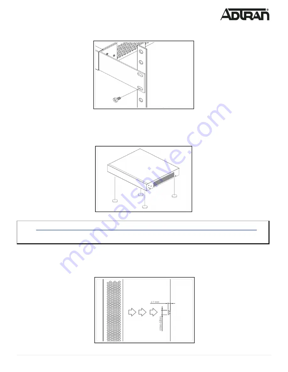
3. Have an assistant hold the unit in position, with the oval holes in the brackets aligned with the mounting holes in the rack posts, as you insert two 

rack screws and tighten them with the appropriate screw driver. 

Figure 4. Attaching Brackets to the Rack Post

Mounting the Switch on a Desk or Shelf

To mount the switch on a desk or shelf, complete the following steps.

1. Verify that the desk or shelf is sturdy enough to support the switch. 
2. Attach the four adhesive rubber feet to the bottom of the switch.

Figure 5. Attaching the Rubber Feet

Mounting the Switch on a Wall

To mount the switch on a wall, complete the following steps.

1. Using the mounting holes on the bottom of the unit as a template, install two #6 PAN head screws (0.75-inch) in the appropriate location on the wall. 

Be aware of the dimensional limitations of the screws.

Figure 6. Install Screws in the Wall

CAUTION!

f

Desk or shelf mounting of the equipment should be such that the amount of air flow required for safe operation of the equipment is not compromised. 

Allow 1-inch clearance on the top and sides of the unit for sufficient air flow.

Summary of Contents for NetVanta 1560-08

Page 1: ...n instructions before installing or servicing this equipment NetVanta 1560 08 SYSTEM CONSOLE USB RESET 1 2 3 4 5 6 7 8 9 10 9 10 RESET Button Port Status LEDs SYS LED CONSOLE Port 10 100 1000 RJ 45 Po...

Page 2: ...he chassis in the stationary equipment rack Allow 1 inch of clearance between units NOTE g Refer to the national state and local electrical codes for the requirements for power grounding wiring and in...

Page 3: ...ach the four adhesive rubber feet to the bottom of the switch Figure 5 Attaching the Rubber Feet Mounting the Switch on a Wall To mount the switch on a wall complete the following steps 1 Using the mo...

Page 4: ...be mounted in the face down orientation when wall mounted NOTE g The installation of this product must comply with the national state and local electrical code requirements as applicable The AC branc...

Page 5: ...h is connected to a DHCP server skip to Step 3 2 Reconfigure the PC s IP address and subnet mask as below so that it can communicate with the switch For example the method to change the PC s IP addres...

Page 6: ...e needed PC with VT100 terminal emulation software Micro USB to USB cable or a DB 9 to RJ45 Serial Cable the cables are provided along with the unit To initially configure the switch using the CLI com...

Page 7: ...ving packets and the connection speed is 1 Gbps Amber On The port is enabled has established a link to connected device and the connection speed is 100 Mbps Flashing The port is transmitting receiving...

Page 8: ...quipment in a residential area is likely to cause harmful interference in which case the user will be required to correct the interference at his own expense CAN ICES 003 A NMB 003 A CAUTION f This pr...

Reviews: